Do you have a question about the Pilz PNOZ e1.1p and is the answer not in the manual?
States the validity period of the documentation.
Provides instructions on how to use the manual effectively.
Explains important symbols used throughout the manual.
Describes the primary application and purpose of the safety relay.
Mentions compliance requirements with relevant safety regulations.
Explains the necessity of performing a safety assessment before unit use.
Specifies requirements for personnel involved in product assembly and operation.
Outlines the terms and conditions for warranty claims and liability.
Provides guidelines for the proper disposal of the electronic device.
Lists the key safety requirements and features of the relay.
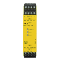
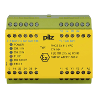
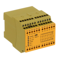
Shows the functional block diagram and terminal layout of the unit.
Explains different operating modes like single-channel and dual-channel.
Details the function and checks of the feedback loop.
Explains the logic inputs for connecting multiple units via AND/OR logic.
Guides on choosing appropriate sensors compatible with the unit.
Provides detailed instructions and guidelines for wiring the unit.
Details the supply voltage requirements and connection methods.
Explains how to wire the input circuit for various trigger elements.
Describes how to connect the start circuit for automatic or monitored start.
Explains the connection and function of the feedback loop.
Illustrates the feedback loop control using external contactors.
Details how to logically connect multiple PNOZelog and PNOZmulti units.
Explains the connection of logic inputs S35 and S36 for AND/OR operations.
Warns about the dangers of muting the safety function using the OR input.
Loads connected to safety outputs AND-linked to other units.
Loads connected to safety outputs AND-linked to another unit.
Illustrates logic connection between units using external contactors.
Explains the meaning of the unit's status LEDs (POWER, CH.1, CH.2).
Describes how fault conditions are indicated by LED flashing.
Lists LED states, faults, and corresponding remedies.
Explains the relationship between LED flashes and error codes.
Details remedies for specific error codes.
Provides additional remedies for various error codes.
Provides physical dimensions and electrical specifications.
Details input/output characteristics and timing parameters.
Covers environmental suitability and mechanical properties.
Presents safety ratings (PL, SIL) required for plant/machine safety.
Procedure for safely removing plug-in terminals.
Lists product types, features, and order numbers.
Provides contact information for technical support and company details.
| Product type | Safety relay |
|---|---|
| Type | PNOZ e1.1p |
| Supply voltage | 24 V DC |
| Auxiliary contacts | 1 |
| Rated current | 6 A |
| Stop category | 0 |
| Safety category | 4 |
| Mounting Type | DIN rail |
| Width | 22.5 mm |
| Height | 87 mm |
| Depth | 121 mm |
| Weight | 200 g |
| Protection class | IP20 |
| Ambient temperature range | -10 to 55 °C |