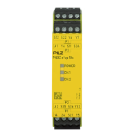
PNOZ e1.1p
Operating Manual PNOZ e1.1p
21238-EN-06
11
Wiring
Please note:
} Information given in the "Technical details [ 27]" must be followed.
} Use copper wire that can withstand 60/75°C.
} Calculation of the max. cable length l
max
in the input circuit:
R
lmax
= max. overall cable resistance (see Technical details [ 27])
R
l
/km = cable resistance/km
} Cables that have to be laid outside the control cabinet must be protected from mechan-
ical damage, e.g. by installing them in a conduit.
} The unit and the input circuits must always be supplied by a single power supply.
} Safety outputs 14 and 24 should exclusively be used for safe applications.
} The safety outputs must not be connected to control inputs.
} To suppress the pulse on switching off at safety outputs 14 and 24, use the terminal
block with filter (see Order reference [ 31]).
} You must comply with the idling capacity at safety outputs 14 and 24 (see Technical
details [ 27]).
} Do not connect undesignated terminals.
} Output Y32 is an auxiliary output, e.g. for communication with a PLC or text display.
} Auxiliary output Y32 shouldnot be used for safety circuits!
} Only contactors with positive-guided contacts should be used for safety functions.
} Use freewheel diodes to drive inductive loads (e.g. contactors or relays) with the safety/
auxiliary outputs.
} When connecting magnetically operated, reed proximity switches, ensure that the max.
peak inrush current (on the input circuit) does not overload the proximity switch.
} The power supply must comply with the regulations for extra low voltages with protect-
ive electrical separation (SELV, PELV) in accordance with VDE 0100, Part 410.
} Ensure the wiring and EMC requirements of IEC 60204-1 are met.
} Terminal Y5 is provided for Pilz-internal diagnostic purposes.

 Loading...