Do you have a question about the Pilz PNOZ e3.1p and is the answer not in the manual?
Specifies the current validity period of the product manual.
Guidance on how to effectively read and utilize the manual.
Explains the meaning of warning symbols and their importance.
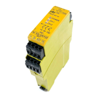
Defines the proper applications and usage of the safety relay.
Outlines relevant safety standards and directives for machine operation.
Emphasizes the need for a safety assessment of the overall plant/machine.
Specifies requirements for personnel involved in product installation and operation.
Conditions under which warranty and liability claims become invalid.
Instructions for the environmentally sound disposal of the device.
Details on safety outputs, connection options, and LED indicators.
Information on logic inputs for interlinking and feedback loop monitoring.
Key safety characteristics like redundancy and self-monitoring.
Visual representation of the device's internal structure and terminal layout.
Explains how the input circuit functions based on sensor states.
Describes the process and error detection for the feedback loop.
How logic inputs S35 and S36 enable interlinking of units.
Details the different operational modes like dual-channel and start types.
Recommendations for installing the unit in control cabinets and on DIN rails.
Critical information on wiring practices, cable types, and EMC measures.
Instructions for connecting the AC or DC supply voltage to the unit.
How to wire the input circuit for dual-channel operation.
Configuration options for automatic or manually monitored startup.
How to connect external contacts or leave the feedback loop unconnected.
Guidelines for logically connecting different Pilz unit series.
How unit SIL/PL values affect the overall safety circuit.
Notes on connecting safety outputs to logic inputs and potential delays.
Detailed diagrams showing AND/OR logic connections using S35/S36.
Critical warning about the misuse of OR function for muting.
Demonstrates AND-linking safety outputs across multiple units.
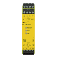
Explains the meaning of the POWER, CH.1, and CH.2 LEDs.
How LEDs indicate the unit's operational status and errors.
How supply interruptions and faults are detected and signaled.
Visual representation of fault codes through LED flashing patterns.
Comprehensive table mapping error codes to descriptions and solutions.
Physical size specifications of the safety relay.
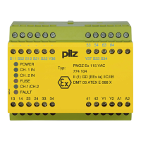
Core specifications including certifications, voltage, and current ratings.
Details on voltage, current, and resistance for input circuits.
Information on safety outputs, auxiliary outputs, and load switching limits.
Key timing parameters such as switch-on delay and response times.
Operating and storage conditions, EMC, and vibration standards.
Details on housing, terminals, mounting, and material composition.
Conductor cross-section, stripping length, and overall dimensions.
Safety integrity levels (SIL) and performance levels (PL) with mission time data.
Procedure for safely detaching plug-in terminal blocks.
Part numbers and ordering information for the product and accessories.
Contact information for technical assistance worldwide.