PNOZ e3.1p
Operating Manual PNOZ e3.1p
21240-EN-09
| 11
} Auxiliary output Y32 shouldnot be used for safety circuits!
} Only contactors with positive-guided contacts should be used for safety functions.
} Use freewheel diodes to drive inductive loads (e.g. contactors or relays) with the safety/
auxiliary outputs.
} When connecting magnetically operated, reed proximity switches, ensure that the max.
peak inrush current (on the input circuit) does not overload the proximity switch.
} The power supply must comply with the regulations for extra low voltages with protective
electrical separation (SELV, PELV) in accordance with VDE 0100, Part 410.
} Terminal Y5 is provided for Pilz-internal diagnostic purposes.
Preparing for operation
Supply voltage
Supply voltage AC DC
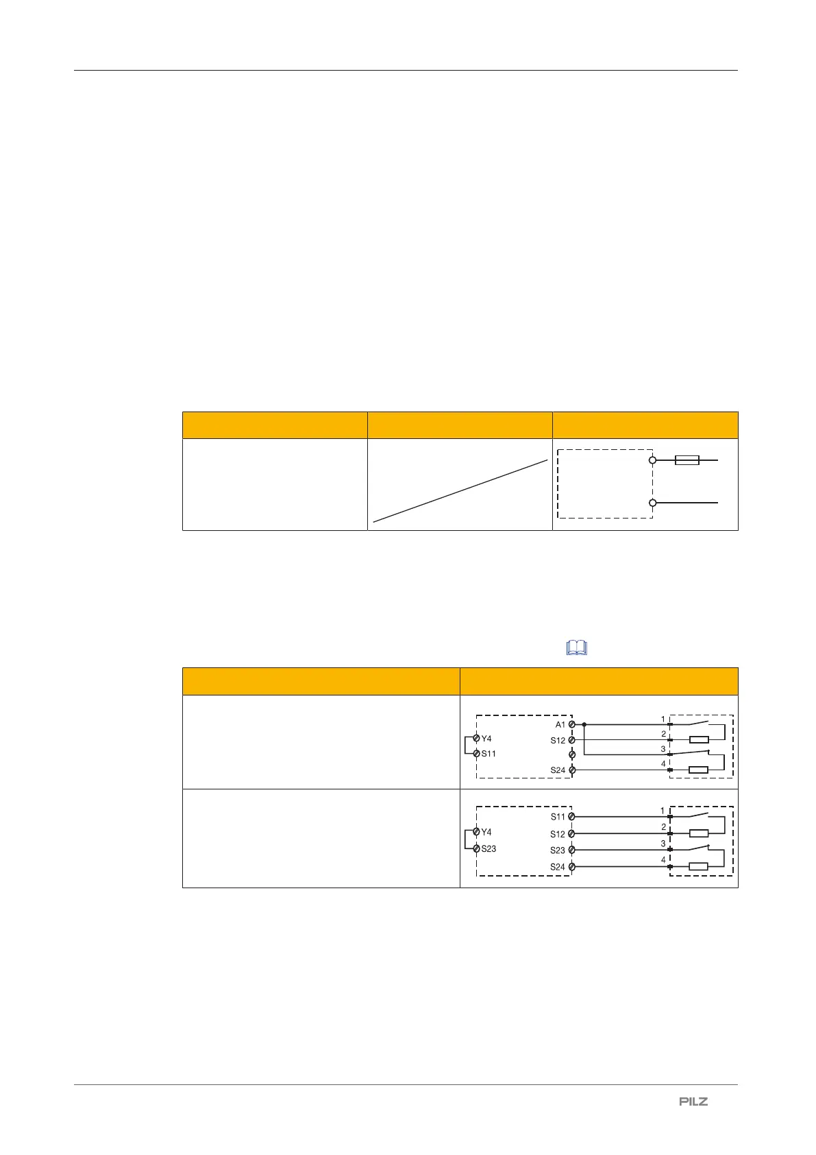
Input circuit
Connect the N/C and N/O contact from the trigger element to the input circuit.
The table describes how the input circuit is wired when the unit is used individually (without
logic input). If units are linked together logically, Y4 must be wired as described in the table
in the section entitled "Logic connection between several units [ 14]".
Input circuit Dual-channel
without detection of shorts across contacts
with detection of shorts across contacts
 Loading...