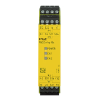
PNOZ e3.1p
Operating Manual PNOZ e3.1p
21240-EN-09
| 10
Installation
CAUTION!
Electrostatic discharge can damage components on the safety sys-
tem!
Ensure against discharge before touching the safety system, e.g. by touch-
ing an earthed, conductive surface or by wearing an earthed armband.
} The unit should be installed in a control cabinet with a protection type of at least IP54.
} Use the notch on the rear of the unit to attach it to a DIN rail (35 mm).
} When installed vertically: Secure the unit by using a fixing element (e.g. retaining bracket
or end angle).
NOTICE
If you are connecting several units logically, please note the guidelines in
the section entitled Logic connection between several units [ 13].
Wiring
Please note:
} Information given in the "Technical details [ 25]" must be followed.
} Use copper wiring with a temperature stability of 60/75 °C.
} To prevent EMC interferences (particularly common-mode interferences) the measures
described in EN60204-1 must be executed. This includes the separate routing of cables
of the control circuits (input, start and feedback loop) from other cables for energy trans-
mission or the shielding of cables, for example.
} Calculation of the max. cable length l
max
in the input circuit:
R
lmax
= max. overall cable resistance (see Technical details [ 25])
R
l
/km = cable resistance/km
} Cables that have to be laid outside the control cabinet must be protected from mechan-
ical damage, e.g. by installing them in a conduit.
} The unit and the input circuits must always be supplied by a single power supply.
} Safety outputs 14 and 24 should exclusively be used for safe applications.
} The safety outputs must not be connected to control inputs.
} To suppress the pulse on switching off at safety outputs 14 and 24, use the terminal block
with filter (see Order reference [ 30]).
} You must comply with the idling capacity at safety outputs 14 and 24 (see Technical
details [ 25]).
} Do not connect undesignated terminals.
} Output Y32 is an auxiliary output, e.g. for communication with a PLC or text display.
 Loading...