Do you have a question about the Pilz PNOZ e1p and is the answer not in the manual?
Defines intended applications and outlines compliance with safety regulations.
Details the need for safety assessment and requirements for qualified personnel.
Describes key safety features like redundancy and self-monitoring for reliable operation.
Details various operating modes like single-channel, dual-channel, and different start types.
Illustrates wiring for supply voltage and various input circuit configurations.
Shows wiring configurations for automatic and monitored start circuits.
Details how LED indicators display faults and provides initial remedies.
Explains error codes based on LED flash patterns and provides detailed diagnostic tables.
Lists safety integrity levels (SIL) and performance levels (PL) according to relevant standards.
The PNOZ e1p safety relay is designed to provide a safety-related interruption of a safety circuit, meeting the requirements of EN 60947-5-1 and EN 60204-1. It is suitable for applications involving E-STOP pushbuttons, safety gates, light grids, and safety switches with detection of shorts across contacts.
The PNOZ e1p operates by detecting the set operating mode during an initialization phase, indicated by a continuously lit "POWER" LED. Once initialized, the unit is ready for operation.
When the input circuit is closed (e.g., an E-STOP pushbutton is not operated), high signals are present at safety outputs 14 and 24, and auxiliary output Y32. The "CH.1" and "CH.2" LEDs are lit. Conversely, when the input circuit is opened (e.g., an E-STOP pushbutton is operated), low signals are present at these outputs, and the "CH.1" and "CH.2" LEDs turn off.
The device incorporates a feedback loop connected in series to the start circuit. Before a safety output is switched on, a test verifies that the contacts in the feedback loop are closed. If a contact is open, an error is detected, and the CH.1 and CH.2 LEDs flash alternately. The unit cannot be switched back on until the feedback loop is closed and the safety function is reset. In automatic start mode, the feedback loop contacts are also checked when the output signal transitions from high to low. If a contact remains open 150 ms after this signal change, an error is detected and displayed as a flashing code. Rectifying this error requires switching the supply voltage off and then on again.
The PNOZ e1p supports various operating modes:
From Version 3.0 onwards, the safety outputs of the PNOZ e1p can be logically linked to the safety inputs of other PNOZelog units. This allows for logical connections between PNOZelog units and also with PNOZmulti units. When linking units, the lowest SIL/PL value in the circuit determines the overall SIL/PL value. Safety outputs from PNOZ e1p are suitable for logic connections from unit version 3.0. Each safety output connected to a load can also be connected to the logic inputs of up to four other PNOZelog units. Up to 50 logic inputs from PNOZelog units can be connected to safety outputs with no load. Logical linking introduces delays in switching on and off, which accumulate with each linked unit. All logically linked units must be installed in the same control cabinet or have their connections protected, and must be connected to the same supply voltage.
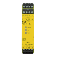
The PNOZ e1p offers semiconductor technology outputs, including two safety outputs, one auxiliary output, and two test pulse outputs. It provides connection options for E-STOP pushbuttons, safety gate limit switches, start buttons, and proximity switches. It can also process signals from output signal switching devices (OSSDs) on light grids.
LED displays provide clear status indications for the supply voltage and the switch status of the safety contacts. Detection of shorts across contacts is performed via the test pulse outputs.
The relay is designed with built-in self-monitoring and redundancy, ensuring that the safety device remains effective even in the event of a component failure. Safety outputs are periodically tested using an off-test.
The safety function of the PNOZ e1p should be checked after initial commissioning and whenever the plant/machine is changed. These checks must be performed by qualified personnel.
During operation, the safety outputs are continuously checked via test pulses. These pulses may cause a humming noise on connected contactors, but this does not affect the function. When measuring voltage at the safety outputs with a multimeter, the test pulses may cause the displayed voltage to be lower than the actual voltage.
The unit indicates status and errors through its LEDs. A continuously lit LED signifies "on," while a flashing LED indicates an error. The "POWER" LED indicates that supply voltage is present and the operating mode is detected, or that the unit is in the initialization phase (flashing). The "CH.1" and "CH.2" LEDs indicate a high signal at safety outputs 14 and 24, respectively.
Fault conditions are indicated by flashing LEDs. Some faults are displayed via periodic flashing, while others use an error code determined by the number of flashes. Error codes are always preceded by three short flashes from LED CH.1 or CH.2, followed by a longer pause, and then flashes at one-second intervals corresponding to the error code digits. Digits are separated by a longer pause. Supply interruptions lasting longer than 20 ms are detected as errors, causing the LEDs to indicate a fault and the safety outputs to carry a low signal, shutting down the machinery. The unit can only be restarted by switching the supply voltage off for at least 1 second and then on again. After any fault is rectified, the supply voltage must be switched off for at least 1 second and then switched back on.
| Type | Safety relay |
|---|---|
| Number of safety outputs | 2 |
| Number of contacts | 2 |
| Contact configuration | 2 x NO |
| Number of safety contacts | 2 |
| Number of auxiliary contacts | 0 |
| Operating voltage | 24 V DC |
| Rated current | 6 A |
| Response time | 20 ms |
| Width | 22.5 mm |
| Rated voltage | 24V DC |
| Max. switching current | 6 A |
| Terminal type | Screw terminals |
| Standards | EN 60204-1 |