EasyManuals Logo

Pilz PNOZ e1p User Manual

Pilz PNOZ e1p
28 pages
To Next Page IconTo Next Page
To Previous Page IconTo Previous Page
Page #12 background imageLoading...
Page #12 background image
PNOZ e1p
Operating Manual PNOZ e1p
21242-EN-13
| 12
Preparing for operation
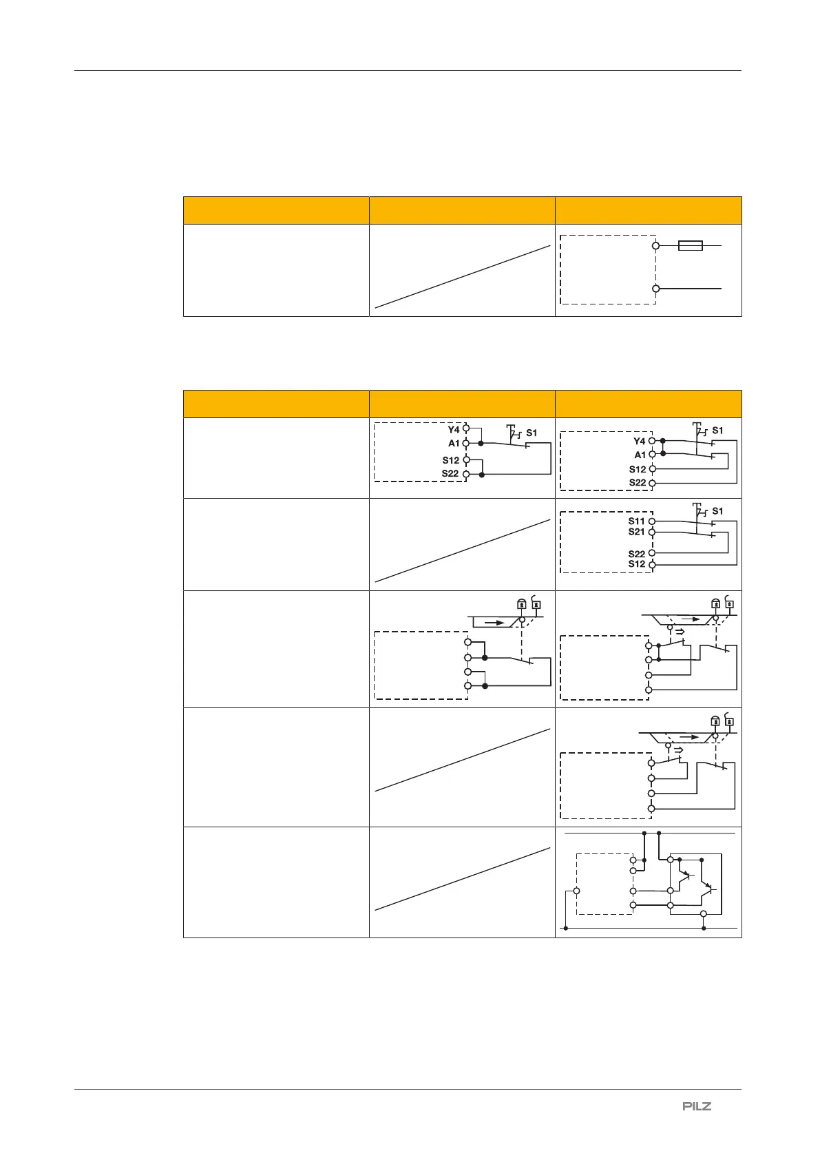
Supply voltage
Supply voltage AC DC
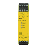
A1
F1
A2
L+
L-
Input circuit
Connect the N/C contact from the trigger element (e.g. E-STOP) to the input circuit.
Input circuit Single-channel Dual-channel
E-STOP
without detection of shorts
across contacts
E-STOP
with detection of shorts
across contacts
Safety gate
without detection of shorts
across contacts
A1
S12
S22
Y4
Y4
S12
S22
A1
Safety gate
with detection of shorts
across contacts
S11
S12
S21
S22
S21
Light guard or safety switch,
detection of shorts across
contacts via ESPE
A1
A2 S12
S22
24 V DC
GND
Y4
The E-STOP pushbutton and safety gate switch symbolise a trigger element with N/C / N/C
combination.

Other manuals for Pilz PNOZ e1p

Questions and Answers:

Question and Answer IconNeed help?

Do you have a question about the Pilz PNOZ e1p and is the answer not in the manual?

Pilz PNOZ e1p Specifications

General IconGeneral
BrandPilz
ModelPNOZ e1p
CategoryRelays
LanguageEnglish

Related product manuals