Do you have a question about the Pilz PNOZ e1vp and is the answer not in the manual?
Information on the validity period of the PNOZ e1vp operating manual.
Guidance on how to effectively use the PNOZ e1vp operating manual for instruction.
Explanation of symbols used in the PNOZ e1vp manual for hazard identification.
Defines the proper applications and usage of the PNOZ e1vp safety relay.
Outlines applicable safety regulations and directives for the PNOZ e1vp.
Describes the necessity of performing a safety assessment before using the unit.
Specifies requirements for competent persons assembling, operating, and maintaining the product.
Details conditions that invalidate warranty and liability claims for the product.
Provides guidance on the proper disposal of electronic devices according to regulations.
Describes the key safety features inherent to the PNOZ e1vp relay.
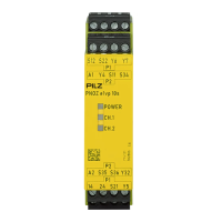
Presents the functional block diagram and terminal configuration of the PNOZ e1vp.
Explains the function and operation of feedback loops for monitoring external contactors.
Describes the use of logic inputs S35 and S36 for connecting multiple units.
Details various operating modes like single-channel, dual-channel, automatic, and monitored start.
Provides guidance on selecting appropriate sensors for the PNOZelog units.
Details the AC and DC supply voltage requirements for the unit.
Explains wiring configurations for the input circuit with E-STOP and safety gates.
Describes wiring for automatic and monitored start circuits for safety gates and E-STOP.
Explains connecting feedback loops and setting delay times for safety output 24.
Details how to set delay times by connecting Y6 and Y7 to specific terminals.
Illustrates wiring examples for setting delay times and feedback loops.
Shows wiring for instantaneous outputs with feedback to Y7 and logic AND/OR connection.
Warns about muting the safety function via the OR input and risks involved.
Illustrates an AND-link of a safety output to other PNOZelog units via logic input S36.
Shows an AND-link of a safety output to another PNOZelog unit via logic input S36.
Demonstrates logic connection between units involving external contactors and setting outputs.
Explains the meaning of LED indicators for POWER, CH.1, and CH.2 status.
Notes that the delay time can be reduced in the event of a fault.
Describes how supply interruptions are detected as errors and the restart procedure.
Explains how fault conditions are indicated by flashing LEDs and error codes.
Details fault conditions, their remedies, and examples of LED flashing patterns.
Describes error code patterns for 1,0 and provides a table for error code interpretation.
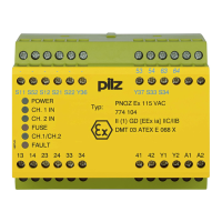
Provides general information including approvals and electrical data for the product.
Details voltage and current specifications for various input circuits of the unit.
Specifies current draw for input circuits and logic inputs.
Details switching capability, safety outputs, auxiliary outputs, and test pulse outputs.
Lists timing specifications like switch-on delay, response times, and delay time.
Covers climatic suitability, temperature ranges, humidity, and EMC requirements.
Details protection types, mechanical data, dimensions, and weight of the unit.
Details switching capability, auxiliary outputs, and test pulse outputs.
Lists timing specifications like switch-on delay, response times, and delay time.
Covers climatic suitability, temperature ranges, and EMC requirements.
Details vibration, protection types, mechanical data, dimensions, and weight.
Emphasizes compliance with safety data for achieving required plant/machine safety levels.
Clarifies that safety function SIL/PL values differ from unit values and recommends PAScal tool.
Lists product types, features, connection types, and their corresponding order numbers.
Details available accessories, such as terminal block filters, with their features and order numbers.