- 1 -
Sicherheitsbestimmungen
• Das Gerät darf nur von Personen installiert
und in Betrieb genommen werden, die mit
dieser Betriebsanleitung und den gelten-
den Vorschriften über Arbeitssicherheit
und Unfallverhütung vertraut sind.
Beachten Sie die VDE- sowie die örtlichen
Vorschriften, insbesondere hinsichtlich
Schutzmaßnahmen.
• Beim Transport, der Lagerung und im
Betrieb die Bedingungen nach EN 60068-
2-6 einhalten (s. technische Daten).
• Die Reparatur des Gerätes darf nur durch
Fa. Pilz GmbH & Co. durchgeführt werden.
Durch Öffnen des Gehäuses oder
eigenmächtige Umbauten erlischt jegliche
Gewährleistung.
• Montieren Sie das Gerät in einen Schalt-
schrank; Staub und Feuchtigkeit können
sonst zu Beeinträchtigungen der Funktio-
nen führen.
• Sorgen Sie an allen Ausgangskontakten
bei kapazitiven und induktiven Lasten für
eine ausreichende Schutzbeschaltung.
• Hinweis für Überspannungskategorie III:
Wenn am Gerät höhere Spannungen als
Kleinspannung (>50 V AC oder
>120 V DC) anliegen, müssen ange-
schlossene Bedienelemente und Sensoren
eine Bemessungsisolationsspannung von
mind. 250 V aufweisen.
Bestimmungsgemäße Verwendung
Das Sicherheitsschaltgerät dient dem
sicherheitsgerichteten Unterbrechen eines
Sicherheitsstromkreises. Das Sicherheits-
schaltgerät erfüllt Forderungen der
EN 60947-5-1, EN 60204-1 und VDE 0113-1
und darf eingesetzt werden in Anwendungen
mit
• Not-Halt-Tastern
• Schutztüren
Das Sicherheitsschaltgerät PNOZ Ex stellt
einen eigensicheren Ausgangsstromkreis
und potentialfreie Kontakte für explosions-
gefährdete Bereiche nach 94/9/EG (ATEX)
zur Verfügung (verwendete Normen:
EN 60079-0:2009, EN 60079-11:2007,
EN 60079-26:2006 und EN 61241-11:2006
für industrielle Anwendungen und
EN 50303:2000 für den Einsatz unter Tage).
ACHTUNG!
Gerät immer außerhalb des
explosionsgefährdeten Bereichs bzw.
in einem Ex-geschützten Einbauraum
montieren. Nur der eigensichere
Ausgangsstromkreis (Klemmen S11,
S12, S21, S22, S33, S34, S52, Y36,
Y37 und GND) und die potentialfreien
Kontakte (Klemmen 53, 54 und 63,
64) dürfen in den explosions-
gefährdeten Bereich (bis Zone 0 bzw.
20) geführt werden.
Das Gerät ist für die Absicherung von
berührungslosen Verdeckungen geeignet, da
ein dynamischer Start möglich ist.
Consignes de sécurité
• L’installation et la mise en service de
l’appareil doivent être effectuées par une
personne qui s’est familiarisée avec le
présent manuel d’utilisation et avec les
presciptions relatives à la sécurité du
travail et à la prévention des accidents.
Respectez les normes locales ou VDE,
particulièrement en ce qui concerne la
sécurité.
• Respectez les exigences de la norme
EN 60068-2-6 lors du transport, du
stockage et de l’utilisation de l’appareil.
(voir "Caractéristiques techniques")
• Cet appareil ne doit être réparé que par la
société Pilz GmbH & Co. L’ouverture de
l’appareil ou sa modification rend la
garantie automatiquement caduque.
• L’appareil doit être monté dans une
armoire, l’humidité et la poussière pouvant
entraîner des dysfonctionnements.
• Veillez à garantir un pouvoir de coupure
suffisant des contacts de sortie en cas de
charges capacitives ou inductives.
• Remarque relative à la catégorie de
surtensions III :
Si l’appareil est alimenté avec des tensions
supérieures à la basse tension (>50 V AC
ou >120 V DC), les éléments de commande
et les capteurs raccordés doivent supporter
une tension d’isolement assignée d’au
moins 250 V.
Utilisation conforme
Le bloc logique de sécurité sert à interrompre
en toute sécurité un circuit de sécurité. Le
bloc logique de sécurité satisfait aux
exigences des normes EN 60947-5-1,
EN 60204-1 et VDE 0113-1 et peut être
utilisé dans des applications avec des
• poussoirs d'arrêt d'urgence
• protecteurs mobiles
Le bloc logique de sécurité PNOZ Ex fournit
un circuit de sortie à sécurité intrinsèque et
des contacts sans potentiel pour les
atmosphères explosibles selon 94/9/CE
(ATEX) (normes utilisées : EN 60079-0:2009,
EN 60079-11:2007, EN 60079-26:2006 et
EN 61241-11:2006 pour les applications
industrielles et EN 50303:2000 pour une
utilisation souterraine).
ATTENTION !
Montez impérativement l'appareil en
dehors de l'atmosphère explosible ou
dans un lieu d'implantation avec
protection Ex. Seuls le circuit de
sortie à sécurité intrinsèque (bornes
S11, S12, S21, S22, S33, S34, S52,
Y36, Y37 et GND) et les contacts
sans potentiel (bornes 53, 54 et 63,
64) peuvent être câblés dans une
atmosphère explosible (jusqu'en
zone 0 ou 20).
L’appareil n’est pas adapté à la surveillance
de barrières immatérielles car un réarme-
ment dynamique est possible.
Safety regulations
• The unit may only be installed and
commissioned by personnel who are
familiar with both these operating
instructions and the current regulations for
health and safety at work and accident
prevention. Ensure VDE and local
regulations are met, especially those
relating to safety.
• Transport, storage and operating condi-
tions should all conform to EN 60068-2-6
(see technical details).
• The unit may only be repaired by
Pilz GmbH & Co. Any guarantee is
rendered invalid if the housing is opened or
unauthorised modifications are carried out.
• The unit should be panel mounted,
otherwise dust and moisture could
adversely affect its function.
• Sufficient fuse protection must be provided
on all output contacts with capacitive and
inductive loads.
• Note for overvoltage category III:
If voltages higher than low voltage
(>50 VAC or >120 VDC) are present on
the unit, connected control elements and
sensors must have a rated insulation
voltage of at least 250 V.
Intended use
The safety relay provides a safety-related
interruption of a safety circuit. The safety
relay meets the requirements of EN 60947-5-
1, EN 60204-1 and VDE 0113-1 and may be
used in applications with
• E-STOP pushbuttons
• Safety gates
The safety relay PNOZ Ex provides an
intrinsically safe output circuit and volt-free
contacts for potentially explosive areas in
accordance with 94/9/EC (ATEX) (standards
applied: EN 60079-0:2009,
EN 60079-11:2007, EN 60079-26:2006 and
EN 61241-11:2006 for industrial applications
and EN 50303:2000 for use underground).
CAUTION!
The unit should always be installed
outside the potentially explosive area
or inside an Ex-protected space. Only
the intrinsically safe output circuit
(terminals S11, S12, S21, S22, S33,
S34, S52, Y36, Y37 and GND) and
the volt-free contacts (terminals 53,
54 and 63, 64) may be brought into
the potentially explosive area (up to
Zone 0 or 20).
The unit is suitable for non-contact barriers
(e.g. light curtains) because a dynamic start
is possible.
19415-3FR-06
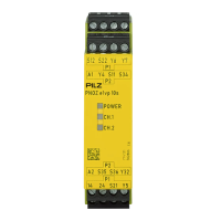
PNOZ Ex
4 D Betriebsanleitung
4 GB Operating instructions
4 F Manuel d'utilisation