PNOZ e3.1p
Operating Manual PNOZ e3.1p
21240-EN-09
| 13
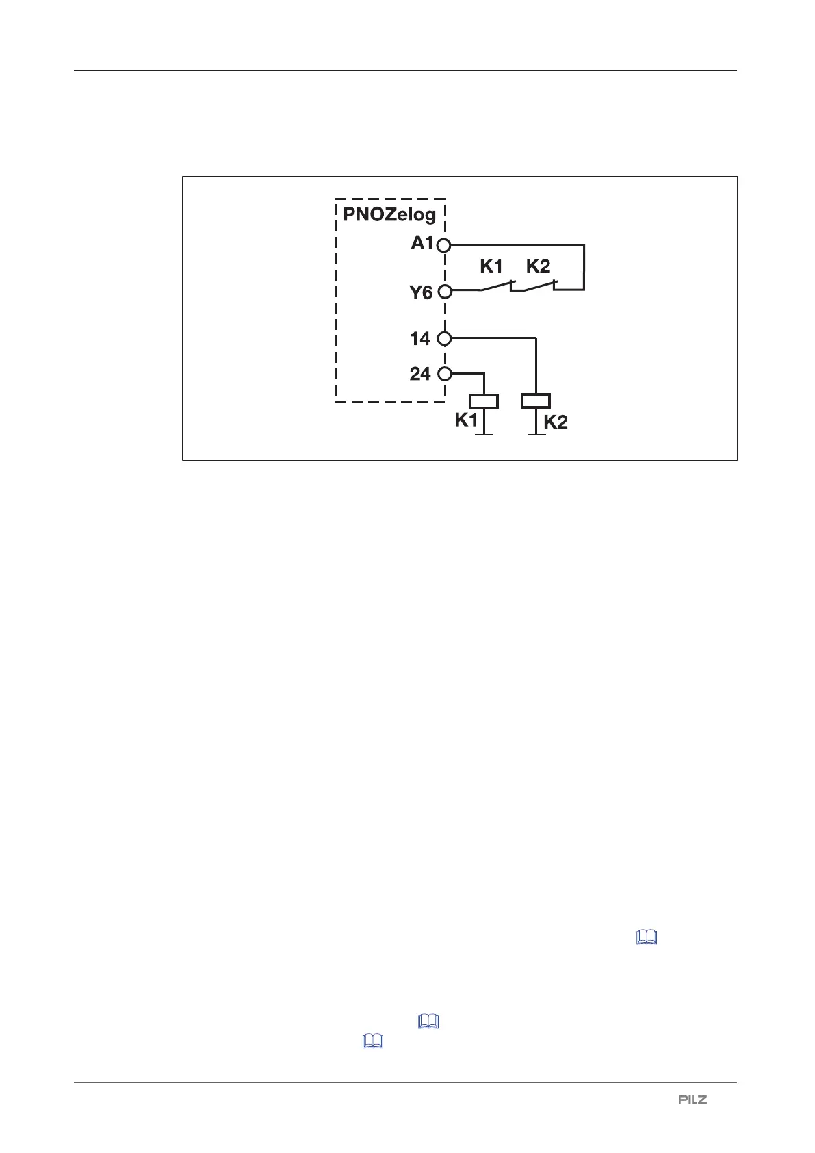
Example
The positive-guided contacts of contactors K1 and K2 control the feedback loop
Logic connection between several units
Units from the PNOZelog product range can be logically connected to each other and to
units from the PNOZmulti product range. On the PNOZelog, input S35 is intended for the
logic OR connection and input S36 for the logic AND connection. Safety outputs 14 and 24
on the PNOZelog are suitable for logic connections.
When linking several units logically, please note:
} When PNOZelog units are linked logically to each other, a safety output from a
PNOZelog unit may be connected to logic inputs from one or more PNOZelog units.
} When linking PNOZelog units logically to PNOZmulti units
– a cascading output from PNOZmulti units may be connected to logic inputs on
PNOZelog units
or
– a safety output from PNOZelog units may be connected to cascading inputs on
PNOZmulti units.
} The unit with the lowest SIL/PL value determines the SIL/PL value of the entire circuit.
} PNOZ e1p, PNOZ e8.1p: These units do not have logic inputs. Their safety outputs can
be used to logically link the units to the logic inputs of other PNOZelog units or to the cas-
cading inputs from PNOZmulti units.
} Safety outputs from the PNOZ e1p are suitable for logic connections from unit version
3.0.
} Each safety output on a PNOZelog unit that is connected to the load may also be connec-
ted to the logic inputs of a maximum of four PNOZelog units (Example 1 [ 15]).
} Up to 50 logic inputs from PNOZelog units can be connected to safety outputs with no
load.
} Logically linking the units leads to delays when switching on and off (see on-delay and re-
sponse time in the Technical details [ 25]). These are added up with each unit that is
logically linked (Example 3 [ 18]).
 Loading...