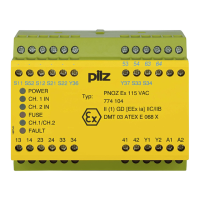
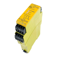
PNOZ e3.1p
Operating Manual PNOZ e3.1p
21240-EN-09
| 14
} Install all the logically linked units in the same control cabinet or ensure that faults regard-
ing the units' connection are excluded, e.g. via protected installation of the connection
cables.
} All linked units must be connected to the same supply voltage.
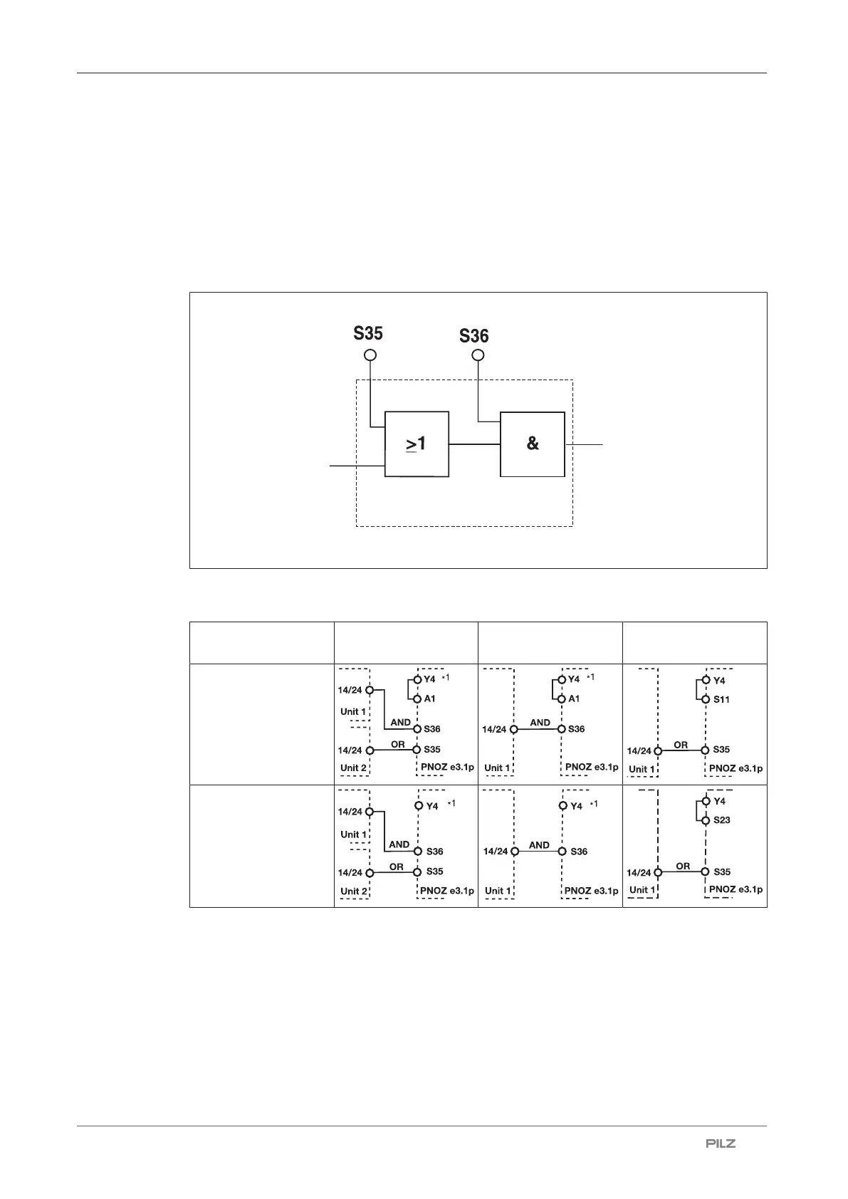
Logic input S35 and S36
The logic inputs are connected to each other as follows:
Input circuit
Safety outputs
Logic inputs S35 and S36 from the PNOZ e3.1p enable additional PNOZelog or PNOZmulti
units to be logically AND/OR connected.
Input circuit Logic AND + OR
connection
Logic AND connec-
tion
Logic OR connec-
tion
without detection of
shorts across con-
tacts
with detection of
shorts across con-
tacts
∗1
Where units are linked logically, Y4 must be wired as shown here (differs from the por-
trayal on the input circuit).
 Loading...