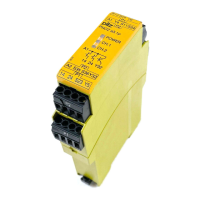
PNOZ e1.1p
Operating Manual PNOZ e1.1p
21238-EN-06
16
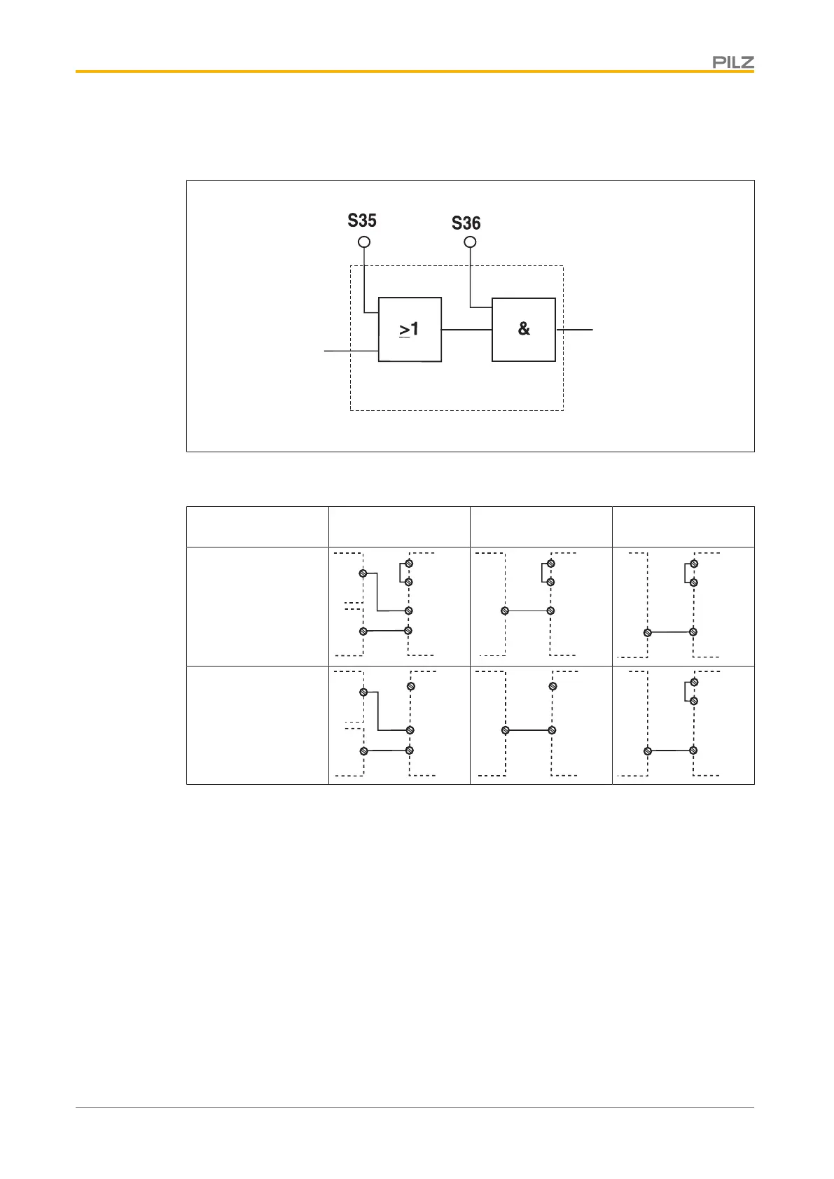
Logic input S35 and S36
The logic inputs are connected to each other as follows:
Input circuit
Safety outputs
Logic inputs S35 and S36 from the PNOZ e1.1p enable additional PNOZelog or PNOZmulti
units to be logically AND/OR connected.
Input circuit Logic AND + OR
connection
Logic AND connec-
tion
Logic OR connec-
tion
without detection of
shorts across con-
tacts
Y4
S36
S35
14/24
14/24
PNOZ e1.1p
Unit 1
Unit 2
AND
OR
A1
*
1
Y4
S36
14/24
PNOZ e1.1p
Unit 1
AND
A1
*
1
Y4
S35
14/24
PNOZ e1.1p
Unit 1
OR
S11
with detection of
shorts across con-
tacts
Y4
S36
S35
14/24
14/24
PNOZ e1.1p
Unit 1
Unit 2
AND
OR
*
1
Y4
S36
14/24
PNOZ e1.1p
Unit 1
AND
*
1
Y4
S35
14/24
PNOZ e1.1p
Unit 1
OR
S21
∗1
Where units are linked logically, Y4 must be wired as shown here (differs from the por-
trayal on the input circuit).

 Loading...