- 4 -
➀ "NOT-AUS" symbolisiert Öffnerkontakt
des Auslöseelements
Sicherheitsschaltgerät in Betrieb
nehmen
Inbetriebnahme vorbereiten
Beachten Sie bei der Vorbereitung der
Inbetriebnahme:
• Das Gerät und die Eingangskreise müssen
immer aus einem Netzteil versorgt werden.
• Verwenden Sie Leitungsmaterial aus
Kupferdraht mit einer Temperaturbe-
ständigkeit von 60/75°C.
• Berechnung der max. Leitungslänge I
max
am Eingangs-, Start und Rückführkreis:
R
lmax
R
l
/ km
I
max
=
R
lmax
= max. Gesamtleitungs-
widerstand (s. technische Daten)
R
l
/km = Leitungswiderstand/km
• Ausgang 14, 24: bei Leerlauf eine
Kapazität bis max. 2 nF ansteuerbar
• Setzen Sie die Sicherheitsausgänge 14
und 24 ausschließlich für sichere
Anwendungen ein. Die Sicherheits-
ausgänge dürfen nicht mit SPS-Eingän-
gen verbunden werden.
Um die Ausschaltimpulse an den
Halbleiterausgängen 14 und 24 zu
unterdrücken, setzen Sie die Reihen-
klemme mit Filter Bestellnummer 774195
oder 774196 ein.
• Der Ausgang Y32 ist ein Hilfsausgang
z. B. für die Kommunikation mit einer SPS
oder einer Anzeige.
• Das Verknüpfen von PNOPZ e1p ist erst
ab Version 3.0 zulässig.
• Sicherheitsausgänge, an denen Lasten
angeschlossen sind, dürfen zusätzlich mit
den Sicherheitseingängen von max. 4
PNOZelog-Geräten verbunden werden.
• Verwenden Sie Freilaufdioden, wenn Sie
mit den Sicherheits-/Hilfsausgängen
Schütze oder Relais ansteuern.
Betriebsbereitschaft herstellen
• Legen Sie die Versorgungspannung an:
Klemme A1(+) : +24 V DC
Klemme A2(-) : 0 V
• Legen Sie die Betriebsart mit/ohne
Querschlusserkennung durch Verdrahten
des Eingangskreises fest.
➀ “E-STOP” symbolises N/C contact
on the trigger element
➀ „Arrêt d’urgence“ symbolise le contact à
de l'élément de commande
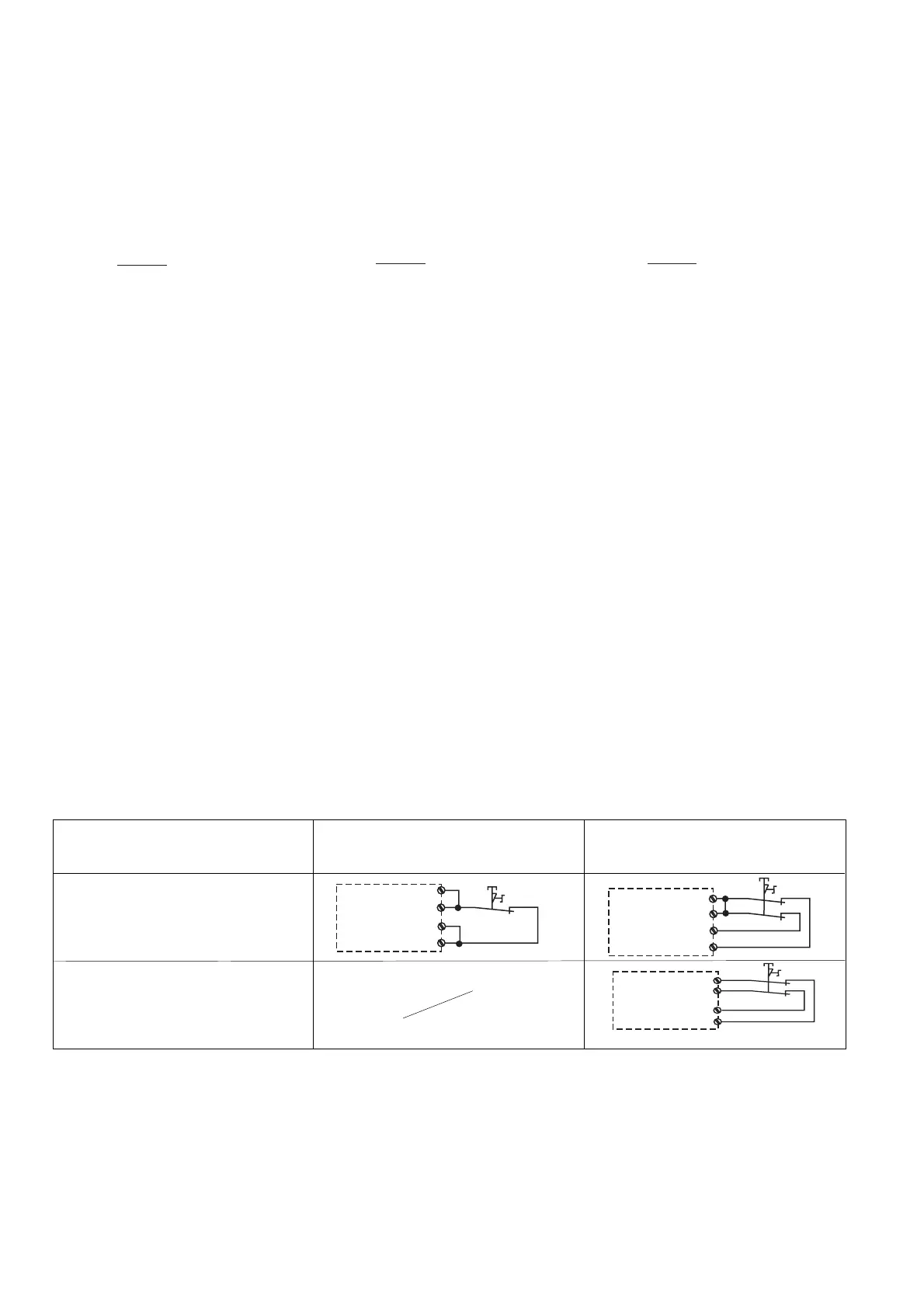
Eingangskreis
Input circuit
Circuit d’entrée
Einkanalig
Single-channel
Commande par 1 canal
Zweikanalig
Dual-channel
Commande par 2 canaux
ohne Querschlusserkennung
without detection of shorts across contacts
sans détection des court-circuits
mit Querschlusserkennung
with detection of shorts across contacts
avec détection des court-circuits
S12
S22
S1
A1
Y4
S12
S11
S21
S1
S22
S12
S22
S1
A1
Y4
➀
➀
➀
Commissioning the safety relay
Preparing for commissioning:
Please note the following when preparing for
commissioning:
• Voltage for the unit and the input circuits
must always be provided from a single
power supply.
• Use copper wire that will withstand
temperatures of 60/75°C.
• Calculating the max. cable length I
max
at
the input circuit, reset circuit and feedback
loop:
R
lmax
R
l
/ km
I
max
=
R
lmax
= max. overall cable resistance (see
Technical details)
R
l
/km = cable resistance/km
• Output 14, 24: when idling, a capacity of a
max. 2 nF can be controlled
• Safety outputs 14 and 24 should be used
for safe applications only. The safety
outputs must not be connected to PLC
inputs.
In order to suppress the pulses on switch-
off on the semiconductor outputs 14 and
24, the terminal block with filter, order
number 774195 or 774196 should be
used.
• Output Y32 should be used exclusively as
an auxiliary output, e.g. for communication
with a PLC or display.
• The PNOZ e1p can only be linked from
version 3.0.
• Safety outputs which have loads
connected may also be linked to the safety
inputs of a max. of 4 PNOZelog units.
• Use flywheel diodes to drive contactors or
relays with the safety/auxiliary outputs.
Preparing the unit for operation
• Connect the supply voltage.
Terminal A1(+) : +24 VDC
Terminal A2(-) : 0 V
• Establish the operating mode with/without
detection of shorts across input contacts
through the wiring of the input circuit.
Mettre en service le bloc logique
Préparer la mise en service :
Pour préparer la mise en service, respectez
les consignes suivantes :
• L’appareil et les circuits d’entrée doivent
toujours être reliés à la même source
d'alimentation.
• Utilisez des fils de câblage en cuivre
supportant des températures 60/75°C.
• Calcul de la longueur de conducteur I
max
sur le circuit d’entrée, le circuit de
réarmement et boucle de retour :
R
lmax
R
l
/ km
I
max
=
R
lmax
= Résistivité de câblage totale max.
(voir les caractéristiques techniques)
R
l
/km = résistance du câble/km
• Sortie 14, 24 : en cas de coupure à vide,
capacité max. de 2 nF pilotable.
• Utilisez les sorties de sécurité 14 et 24
exclusivement dans les circuits de
sécurité. Les sorties de sécurité ne doivent
pas être raccordées à des entrées d’API.
Pour supprimer l'impulsion de coupure aux
sorties statiques 14 et 24, utilisez les
bornes avec filtre, référence 774195 ou
774196.
• Utilisez la sortie Y32 exclusivement
comme sortie d'information pour la
communication par ex. avec un API ou un
afficheur.
• Le couplage de PNOZ e1p n’est permis
qu’à partir de version 3.0.
• Les sorties utilisées pour piloter des
charges, peuvent être raccordées en plus
au max. à 4 entrées de sécurité de relais
de la gamme PNOZelog.
• Utilisez des diodes de roue libre lorsque
vous commandez des contacteurs ou des
relais au moyen des sorties de sécurité/
d’information.
Mettre en œuvre le système
• Appliquez la tension d’alimentation.
borne A1(+) : + 24 V CC
borne A2(-) : 0 V
• Choisissez le mode avec/sans détection
des court-circuits par câblage du circuit
d’entrée.

 Loading...