µController
µController
0 V
T0
T1 T2 T3
Taktausgänge
Test pulse outputs
Sorties
impulsionnelles
Halbleiterausgänge, Hilfsausgang,
Versorgungsanschlüsse
Semiconductor outputs,
auxiliary output, supply connections
Sorties statiques, sorties information,
bornes d'alimentation
13 14 23
24
I19 A1
Eingänge
Inputs
Entrées
Interface
Diagnosemodul
diagnostic module
module de
diagnostic
O4 O5
Relaisausgänge
Relay outputs
Sorties de relais
24 VOA0O3O2O1O0
A1 A2 A2
Netzteil
Power supply
Alimentation
I18I17I16I15I14I13I12I11I10I9I8I7I6I5I4I3I2I1I0
Interface
Erweiterungsmodule
expansion modules
modules d'extension
Interface
Chipkarte
chip card
carte à puce
RS 232
X4
Koppelschnittstelle
Coupling interface
Interface de couplage
CI+ CI- CO+ CO-
X1 X2 X3
X6X5 X7
Gerätemerkmale:
• 20 Eingänge für den Anschluss von NOT-
AUS, Zweihand-Taster, Schutztür,
Lichtvorhang, Scanner, Zustimmungs-
schalter, PSEN, Betriebsartenwahlschalter
• Ausgänge in Halbleitertechnik:
- 2 Sicherheitsausgänge nach
EN 954-1, 12/96, Kat. 4 oder
4 Sicherheitsausgänge nach
EN 954-1, 12/96, Kat. 3
- 1 Hilfsausgang
• Relaisausgänge:
1 Sicherheitskontakt nach
EN 954-1, 12/96, Kat. 4 oder
2 Sicherheitskontakte nach
EN 954-1, 12/96, Kat. 2
• 4 Taktausgänge
• konfigurierbar mit PNOZmulti Configurator
• konfigurierte Sicherheitsschaltungen sind
mit Chipkarte einlesbar
• max. 8 Erweiterungsmodule anschließbar
• Statusanzeigen
• Querschlussüberwachung durch Taktaus-
gänge an den Eingängen
• Querschlussüberwachung zwischen den
Sicherheitsausgängen
• steckbare Klemmen, wahlweise mit
Käfigzugfederanschluss oder
Schraubanschluss
Funktionsbeschreibung
Arbeitsweise:
Die Funktionsweise der Ein- und Ausgänge
des Sicherheitssystems hängt von der mit
dem PNOZmulti Configurator erstellten
Sicherheitsschaltung ab. Die Sicherheits-
schaltung wird mit einem Chipkarten-
lesegerät oder über die RS 232-Schnittstelle
auf die Chipkarte in das Basisgerät übertra-
gen. Das Basisgerät hat 2 Micro-Controller,
die sich gegenseitig überwachen. Sie werten
die Eingangskreise des Basisgeräts und der
Erweiterungsmodule aus und schalten
abhängig davon die Ausgänge des Basis-
geräts und der Erweiterungsmodule.
Unit features:
• 20 inputs for connecting E-STOP, two-
hand buttons, safety gate, light curtain,
scanner, enable switch, PSEN, operating
mode selector switch
• Outputs with semiconductor technology:
- 2 safety outputs in accordance with
EN 954-1, 12/96, Cat. 4 or 4 safety
outputs in accordance with
EN 954-1, 12/96, Cat. 3
- 1 auxiliary output
• Relay outputs:
1 safety contact in accordance with
EN 954-1, 12/96, Cat. 4 or 2 safety
contacts in accordance with
EN 954-1, 12/96, Cat. 2
• 4 test pulse outputs
• Can be configured using the PNOZmulti
Configurator
• Configured safety circuits can be read in
via the chip card
• Max. 8 expansion modules can be
connected
• Status indicators
• Test pulses used to detect shorts across
the inputs
• Monitors shorts between the safety
outputs
• Plug-in terminals, either with cage clamp
connection or screw connection
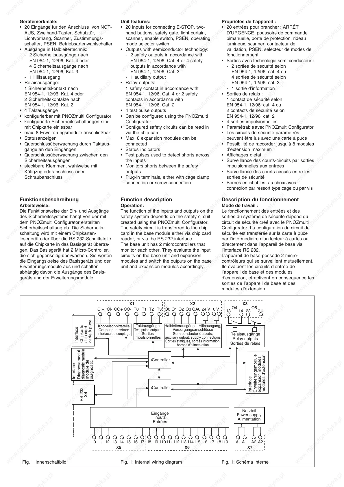
Function description
Operation:
The function of the inputs and outputs on the
safety system depends on the safety circuit
created using the PNOZmulti Configurator.
The safety circuit is transferred to the chip
card in the base module either via chip card
reader, or via the RS 232 interface.
The base unit has 2 microcontrollers that
monitor each other. They evaluate the input
circuits on the base unit and expansion
modules and switch the outputs on the base
unit and expansion modules accordingly.
Propriétés de l’appareil :
• 20 entrées pour brancher : ARRÊT
D’URGENCE, poussoirs de commande
bimanuelle, porte de protection, rideau
lumineux, scanner, contacteur de
validation, PSEN, sélecteur de modes de
fonctionnement
• Sorties avec technologie semi-conducteur :
- 2 sorties de sécurité selon
EN 954-1, 12/96, cat. 4 ou
4 sorties de sécurité selon
EN 954-1, 12/96, cat. 3
- 1 sortie d’information
• Sorties de relais :
1 contact de sécurité selon
EN 954-1, 12/96, cat. 4 ou
2 contacts de sécurité selon
EN 954-1, 12/96, cat. 2
• 4 sorties impulsionnelles
•
Paramétrable avec PNOZmulti Configurator
• Les circuits de sécurité paramétrés
peuvent être lus avec une carte à puce
• Possibilité de raccorder jusqu’à 8 modules
d’extension maximum
• Affichages d’état
• Surveillance des courts-circuits par sorties
impulsionnelles aux entrées
• Surveillance des courts-circuits entre les
sorties de sécurité
• Bornes enfichables, au choix avec
connexion par ressort type cage ou par vis
Description du fonctionnement
Mode de travail :
Le fonctionnement des entrées et des
sorties du système de sécurité dépend du
circuit de sécurité créé avec le PNOZmulti
Configurator. La configuration du circuit de
sécurité est transférée sur la carte à puce
par l’intermédiaire d’un lecteur à cartes ou
directement dans l’appareil de base via
l’interface RS 232.
L’appareil de base possède 2 micro-
contrôleurs qui se surveillent mutuellement.
Ils évaluent les circuits d’entrée de
l’appareil de base et des modules
d’extension, et activent en conséquence les
sorties de l’appareil de base et des
modules d’extension.
Fig. 1 Innenschaltbild Fig. 1: Internal wiring diagram Fig. 1: Schéma interne

 Loading...


