Do you have a question about the Pilz PNOZ m0p and is the answer not in the manual?
Documentation validity for the PNOZ m0p product and its update policy.
Guidance on keeping the documentation for future instruction and reference.
Summary of the manual's content, structure, and order of information.
Explanation of symbols used to highlight important information like danger, warning, caution, notice, and information.
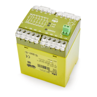
Describes the physical composition and modular structure of the PNOZ m0p unit.
Lists the standard items included with the PNOZ m0p product upon purchase.
Details the key features and capabilities of the PNOZ m0p, including I/O and interfaces.
Explains the role and types of chip cards required for the PNOZ m0p's operation.
Visual representation of the front panel of the PNOZ m0p and PNOZ m0p ETH units.
Detailed view of the PNOZ m0p's front panel components and connectors.
Detailed view of the PNOZ m0p ETH's front panel components and connectors.
Identifies and explains the function of each component and LED on the unit's front view.
Defines the specific applications and purpose for which the PNOZmulti safety system is designed.
Specifies the minimum software version requirements for the PNOZmulti Configurator.
Outlines general safety regulations and guidelines for handling and operating the equipment.
Describes the necessary qualifications and responsibilities of personnel involved in operation.
Conditions under which warranty and liability claims become invalid.
Guidelines for the proper and safe disposal of the electronic equipment.
Crucial safety requirements to ensure safe operation and prevent hazards.
Details the inherent characteristics and design features of the PNOZ m0p unit.
Explains the built-in safety features like redundancy and self-monitoring for reliable operation.
General overview of how the safety system's functions operate.
Describes the operational logic based on safety circuits, microcontrollers, and LEDs.
Visual representation of the unit's internal architecture and signal flow.
How to access and interpret diagnostic information and error logs.
Information on connecting multiple units together in series or tree structures.
Guidance on integrating safety mats and implementing muting functions.
Overview of the serial and Ethernet interfaces available for communication.
Essential instructions for properly installing the safety system in a control cabinet environment.
Provides the physical dimensions (height, width, depth) of the unit for installation planning.
Instructions on how to connect the base unit with expansion and fieldbus modules using jumpers.
Fundamental rules and best practices for wiring the system components during commissioning.
Details about the Ethernet interfaces, including RJ45 ports and autosensing features.
Explanation of the RJ45 interface functionality and automatic crossover capability.
Specifies the technical requirements for Ethernet connection cables and connectors.
Pin assignments for RJ45 sockets for standard and crossover connections.
Illustrates the RJ45 connector and cable standards for Ethernet connections.
Describes how process data is exchanged with other devices via the Ethernet interface.
Steps and precautions required before the system can be put into operation.
Emphasizes performing function tests after any project changes or downloads.
Detailed procedure for the initial setup and commissioning of the safety system.
Step-by-step guide to loading a safety project onto the base unit using a chip card.
Process for loading a safety project into the base unit via its integrated interface.
Instructions for updating the safety system with a modified project configuration.
Procedure for loading a modified project from a chip card after a device reset.
Steps for loading a modified project using the base unit's integrated interface.
Guidance and examples for connecting power supply and various input circuits to the unit.
A detailed wiring diagram showing a typical setup for E-STOP, gate, and other functions.
Explanation of status indicators and error messages for device diagnostics.
Details on interpreting LED indicators for status and fault conditions on the unit.
Explains the meaning of Ethernet interface LEDs (LNK, TRF) for network status.
Procedure to reset the Ethernet connection settings of the base unit to default values.
Comprehensive specifications covering electrical data, inputs, outputs, times, and environmental data.
Graphs illustrating the expected electrical service life of output relays under different load conditions.
A graph showing the maximum permissible capacitive load for semiconductor outputs based on current.
Lists product types, their features, and associated order numbers for purchasing.
| Input voltage | 24 V DC |
|---|---|
| Supply voltage | 24 V DC |
| Rated voltage | 24 V DC |
| Protection class | IP20 |
| Safety level | PL e |
| Standards | EN ISO 13849-1 |