Pilz GmbH & Co. KG, Felix-Wankel-Straße 2, 73760 Ostfildern, Germany
Telephone: +49 711 3409-0, Telefax: +49 711 3409-133, E-Mail: pilz.gmbh@pilz.de
8-5
8.2 Service life graph of output relays
8 Technical details
8.2Service life graph of output relays8200Service life graph of output relays8-Lebensda uerkurve_Relais_T ext vor Kurve
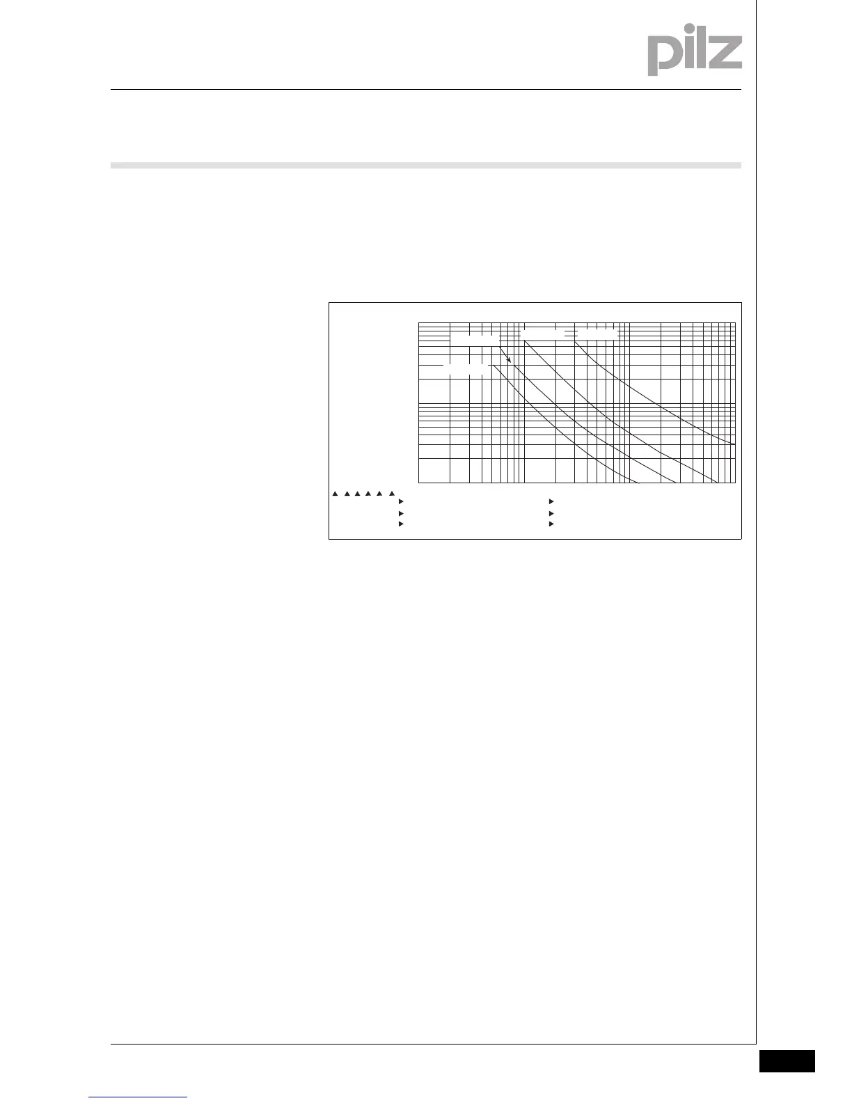
The service life graphs indicate the number of cycles from which failures
due to wear must be expected. The wear is mainly caused by the elec-
trical load; the mechanical load is negligible.
Lebensdaue rkurve SIS_212
Lebensdauerkurve_R elais_Text nach Ku rve_SIS212_SIR-S LR Bsp
Example
` Inductive load: 0.2 A
` Utilisation category: AC15
` Contact service life: 1 000 000 cycles
Provided the application requires fewer than 1 000 000 cycles, the PFH
value (see technical details) can be used in the calculation.
To increase the service life, sufficient spark suppression must be provid-
ed on all output contacts. With capacitive loads, any power surges that
occur must be noted. With contactors, use freewheel diodes for spark
suppression.
Lebensdauerkurve_Relais_Text nach Kurve-2_ Empfehlung Halbleiterausgänge
We recommend you use semiconductor outputs to switch 24 VDC
loads.
10
1
10 100 1000 10000
0.1
DC1: 24 V
AC1: 230 V
DC13: 24 V
AC15: 230 V
D Nennbetriebstrom (A)
GB Nominal operating current (A)
F Courant coupé (A)
E Corriente nominal de servicio (A)
I Corrente di esercizio nominale (A)
NL Nominale bedrijfsstroom (A)
D Schaltspielzahl x 10
3
GB Cycles x 10
3
F Nombre de manuvres x 10
3
E Número de ciclos x 10
3
I Numero dei cicli di commutazione x 10
3
NL Aantal schakelingen x 10
3

 Loading...


