Do you have a question about the Pilz PDP67 F 4 code and is the answer not in the manual?
States the validity period of the documentation for the PDP67 F 4 code products.
Provides guidance on how to use the manual for product installation and commissioning.
Explains the meaning of DANGER, WARNING, CAUTION, NOTICE, and INFORMATION symbols.
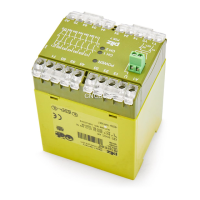
Describes the components and range of the PDP67 F 4 code module.
Lists the key features of the PDP67 F 4 code module, including protection type and connectivity.
Illustrates the physical layout, connectors (X1-X6), and LEDs of the module.
Defines the proper application of the module and lists scenarios considered improper use.
Outlines essential safety rules and specifies requirements for qualified personnel.
Details conditions under which warranty and liability claims become invalid.
Instructs to comply with local regulations for electronic device disposal.
Explains how to connect sensors and the evaluation device to the module.
Presents a schematic illustrating the internal wiring connections of the module.
Describes the meaning of LED indicators for Power, Diag, and Lock statuses.
Provides instructions for mounting the module securely on a flat surface.
Displays the physical dimensions and mounting hole specifications of the module.
Offers important notes and precautions for safe and compliant electrical connections.
Details the pin assignments for the 8-pin M12 female connectors X1 to X4.
Details the pin assignments for the 8-pin M12 female connectors X5 and X6.
Covers connection notes, sensor limits, adapter usage, and correct connection sequence.
Details sensor connection in an independent circuit, including safety precautions and examples.
Covers connecting modules in series, voltage drop, and safety guidelines.
Explains how the module indicates readiness for operation via the "Power" LED.
Describes the meaning of LED indicators for Power, Diag, and Lock statuses.
Lists general information, approvals, voltage, and current load capacity.
Details climatic suitability, ambient, and storage temperature ranges.
Lists material, connection type, protection rating, dimensions, and weight.
Lists order numbers for different PDP67 F 4 code module variants.
Lists order numbers for compatible accessories like adapters and sensor cables.
States compliance with the low voltage directive and provides internet link for the full declaration.
| Supply voltage | 24 V DC |
|---|---|
| Number of safe inputs | 4 |
| Protection type | IP67 |
| Connection type | M12 connector |
| Category | 4 |
| Operating voltage | 24 V DC |
| Housing material | Plastic |
| Protection class | IP67 |
| Type | PDP67 F 4 code |
| Safety classification | PL e |
| Standards | EN ISO 13849-1 |