Preparing for operation
Operating Manual PDP67 F 4 code
1001531-EN-06
17
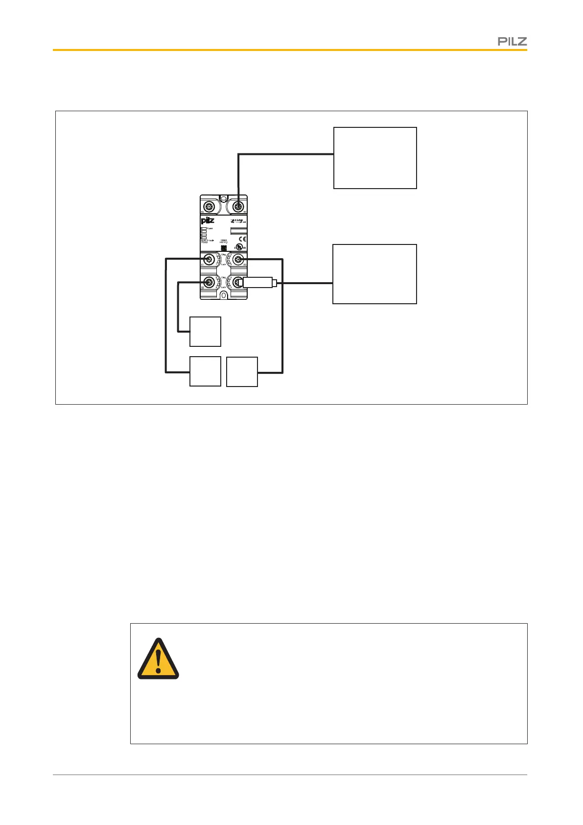
Connection example 2: Connection of three sensors (X1...X3)
PLC
ST
FS
ST: Standard
FS: Fail-Safe
Adapter
*
Evaluation device
PSEN
PSEN
PSEN
*Adapter: PDP67Connectorcs/PDP67 ConnectorcsVA
7.1.2 Series connection of modules
Please note:
} The series connection of the modules is always created with the last free female con-
nector X2 ... . X5 and the X1 female connector of the next module. The adapter PDP67
Connector cs/PDP67 Connector cs VA must be used for connecting the modules in
series.
} The voltage at the last module must not fall below the permitted supply voltage level.
Please refer to the operating manual for the sensors used for the permissible values for
the supply voltage (see "Voltage tolerance" in the chapter entitled "Technical details").
An example of how the voltage drop is calculated can be found in the chapter entitled
"Voltage drop".
WARNING!
Loss of safety function due to incorrect connection sequence!
If the evaluation device is connected to a female connector before or
between the sensors, all sensors connected thereafter will not be evaluated.
Serious injury or death may result, depending on the application.
Always connect the evaluation device to the last free female connector.