Preparing for operation
Operating Manual PDP67 F 4 code
1001531-EN-06
15
7 Preparing for operation
7.1 Connection
Please note:
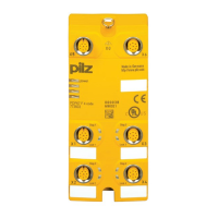
} A maximum of 4 sensors per module can be connected to female connectors X1 ... X4.
Note the current load capacity of the modules (see current load capacity for UB)
} The evaluation device is always connected to the last non-assigned female connector
X2 ... X5.
} The adapter PDP67Connectorcs/PDP67ConnectorcsVA must be used for con-
necting the evaluation device and for connecting the modules in series. The adapter re-
quires the use of a female connector for connecting the supply voltage. This prevents
the risk of a short circuit from contact with the contacts of a male connector.
} The signal outputs (Diag) of the connected sensors are connected to pins 1 to 4 of the
X6 female connector.
} The control commands for magnetic guard locking ("Lock_Unlock") for PSENslock are
connected to pins 5 to 8 of the X6 female connector.
} The sensors must always be connected to the module in consecutive order.
Example:
– Correct: Sensor to female connector X1, X2, X3
– Wrong: Sensor to female connector X1, X2, X4
NOTICE
Connecting the sensors in series increases the delay-on de-energisation.
Please refer to the guidelines contained in the operating manuals for the
sensors.
7.1.1 Independent circuit
WARNING!
Loss of safety function due to incorrect connection sequence!
If the evaluation device is connected to a female connector before or
between the sensors, all sensors connected thereafter will not be evaluated.
Serious injury or death may result, depending on the application.
Always connect the evaluation device to the last free female connector.
NOTICE
When commissioning, activate the safety function of each sensor in the
safety chain and check the correct response of the evaluation device's
safety outputs.

 Loading...