Do you have a question about the Pilz PNOZ m1p and is the answer not in the manual?
Specifies the validity period and scope of the documentation for the PNOZ m1p product.
Provides guidance on how to use the manual for installation and operation of the product.
Explains symbols used in the manual to denote DANGER, WARNING, CAUTION, NOTICE, and INFORMATION.
Details the components included in the PNOZ m1p product range, such as base units and terminators.
Lists the key features of the PNOZ m1p, including configurable options, relay/semiconductor outputs, and input types.
Explains the necessity and types of chip cards required for product configuration and operation.
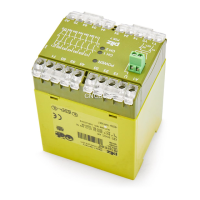
Illustrates the front panel layout of the PNOZ m1p, showing connection terminals and indicators.
Defines the specific applications and environments for which the PNOZmulti control systems are designed, like E-STOP equipment.
Refers to external documents for system requirements related to the PNOZmulti Configurator versions.
Covers safety assessment, qualified personnel, warranty, disposal, and general safety advice for safe operation and maintenance.
Covers integrated protection, general functions, and the block diagram of the control system.
Details diagnostic capabilities, cascading, safety mat/muting, and interface functions for advanced configuration.
Provides guidelines for installing the control system in a control cabinet, including mounting and environmental considerations.
Shows the physical dimensions of the PNOZ m1p unit for planning installation space.
Details the procedure for installing the base unit, including the correct placement of the terminator.
Explains the process of linking the base unit with expansion modules using jumpers and terminators.
Covers general wiring principles and guidelines for safe and effective commissioning.
Details Ethernet interface setup, RJ45 connections, cable requirements, and process data exchange.
Explains function tests, initial commissioning, project loading, and downloading modified projects.
Provides specific wiring examples for inputs, outputs, feedback loops, and general connection information.
Explains the meaning of the LED indicators on the base unit for status and error reporting.
Details the function of LNK and TRF LEDs on Ethernet interfaces for network and data traffic status.
Describes how to test the correct opening of safety contacts on relay outputs as per safety directives.
Provides general information, approvals, and basic electrical data for different product variants.
Details electrical characteristics of inputs, semiconductor outputs, and test pulse outputs.
Specifies data for relay outputs, cascading outputs, Ethernet, and serial interfaces.
Lists safety data (PL, SIL CL, PFH) for CPU and Expansion units.
Provides safety data for various input types and SC/cascaded outputs.
Details safety data for relay outputs, including PL, SIL CL, PFH, and TM values.
Shows graphs illustrating the expected service life of relay contacts based on switching current and load conditions.
Lists the available product types of the PNOZ m1p series with their corresponding order numbers.
Details available accessories such as connection terminals, terminators, and jumpers with their order numbers.
Provides technical support contact details for Americas, Asia, Europe, Scandinavia, and Spain.
Offers the main international hotline number and email address for Pilz technical assistance.
| Supply Voltage | 24 V DC |
|---|---|
| Number of Safe Inputs | 20 |
| Number of Safe Outputs | 8 |
| Number of Standard Outputs | 4 |
| Protection Type | IP20 |
| Expansion Modules | Yes |
| Safety Category | EN ISO 13849-1: PL e |
| Communication Interface | Ethernet |
| Operating Temperature Range | -20°C to +60°C |
| Dimensions (W x H x D) | 45 mm x 121 mm |
| Standards | EN ISO 13849-1, EN 62061, EN 61508 |