Commissioning
Operating Manual PNOZ m1p (ETH)
20878-EN-16
23
6.5 Download modified project to the PNOZmulti system
6.5.1 Load modified project from chip card
To download data via chip card, the existing configuration data must first be deleted (gen-
eral reset of device).
Procedure:
} Switch off the supply voltage.
} Disconnect all the output terminals.
} Jumper OA0-I19 on the base unit.
} Switch on the supply voltage.
When the "DIAG" LED on the base unit flashes, the memory has been cleared. The project
data can now be downloaded:
} Switch off the supply voltage.
} Remove the old chip card from the chip card slot on the base unit.
} Remove the jumper from OA0-I19 on the base unit.
} Insert the chip card containing the current project into the card slot.
} Switch on the supply voltage.
6.5.2 Load modified project via integrated interface
Proceed as described for the initial commissioning
6.6 Connection
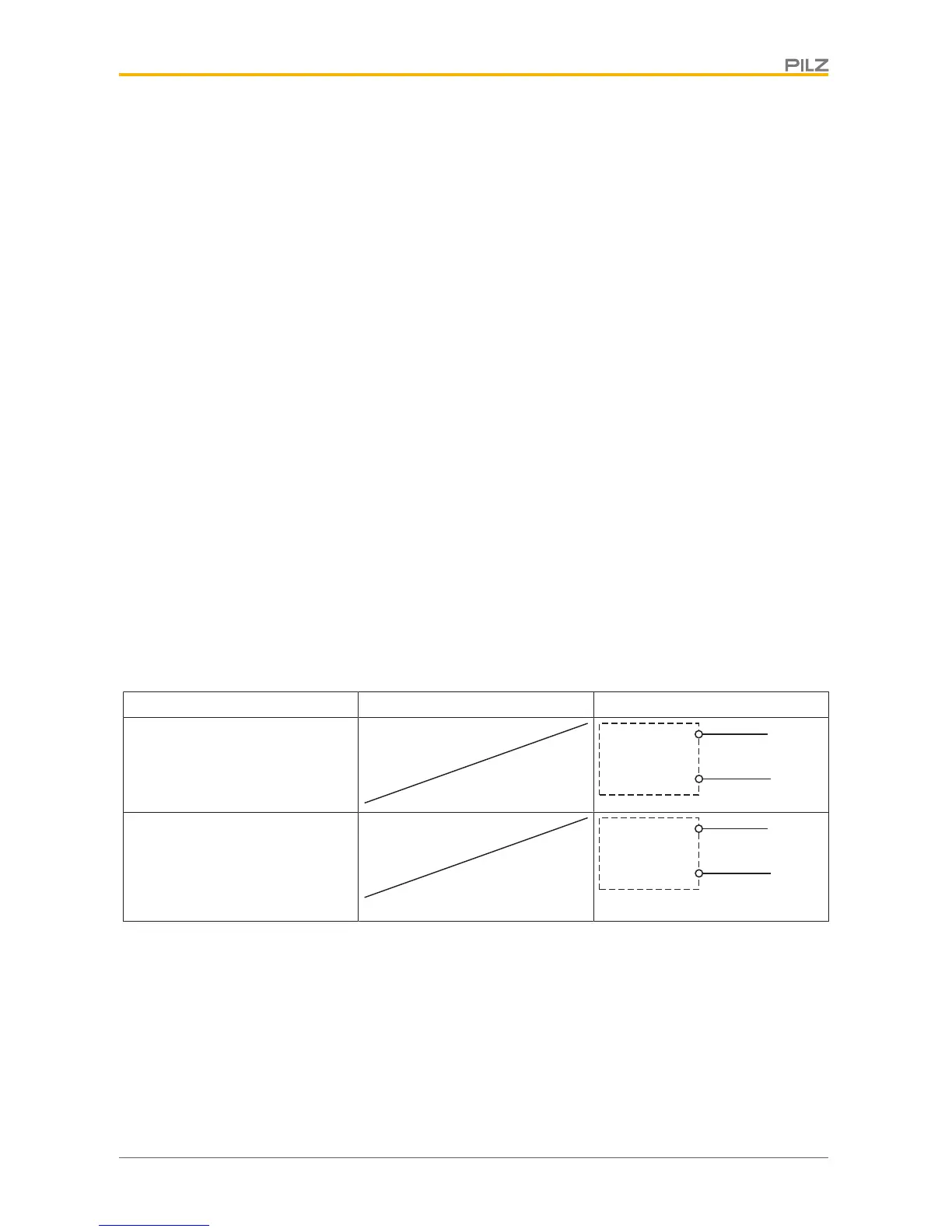
Supply voltage AC DC
For the safety system
(connector X7)
For the semiconductor outputs
(connector X2)
Must always be present, even if
the semiconductor outputs are not
used

 Loading...


