Installation
Operating Manual PNOZ m1p (ETH)
20878-EN-16
15
5 Installation
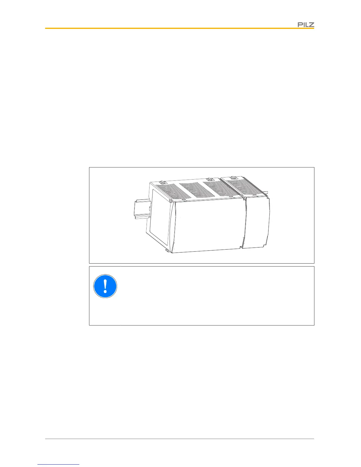
5.1 Control cabinet installation
} The control system should be installed in a control cabinet with a protection type of at
least IP54. Fit the control system to a horizontal mounting rail. The venting slots must
face upward and downward. Other mounting positions could destroy the control system.
} Use the locking elements on the rear of the unit to attach it to a mounting rail. Connect
the control system to the mounting rail in an upright position, so that the earthing
springs on the control system are pressed on to the mounting rail.
} The ambient temperature of the devices in the control cabinet must not exceed the fig-
ure stated in the technical details. Air conditioning may otherwise be required.
} To comply with EMC requirements, the mounting rail must have a low impedance con-
nection to the control cabinet housing.
NOTICE
Damage due to electrostatic discharge!
Electrostatic discharge can damage components. Ensure against discharge
before touching the product, e.g. by touching an earthed, conductive sur-
face or by wearing an earthed armband.

 Loading...


