Installation
Operating Manual PNOZ m1p (ETH)
20878-EN-16
17
5.4 Connecting the base unit and expansion modules
The position of the expansion modules is defined in the PNOZmulti Configurator. The ex-
pansion modules are connected to the left or right of the base unit, depending on the type.
Please refer to the document "PNOZmulti System Expansion" for details of the number of
modules that can be connected to the base unit and the module types.
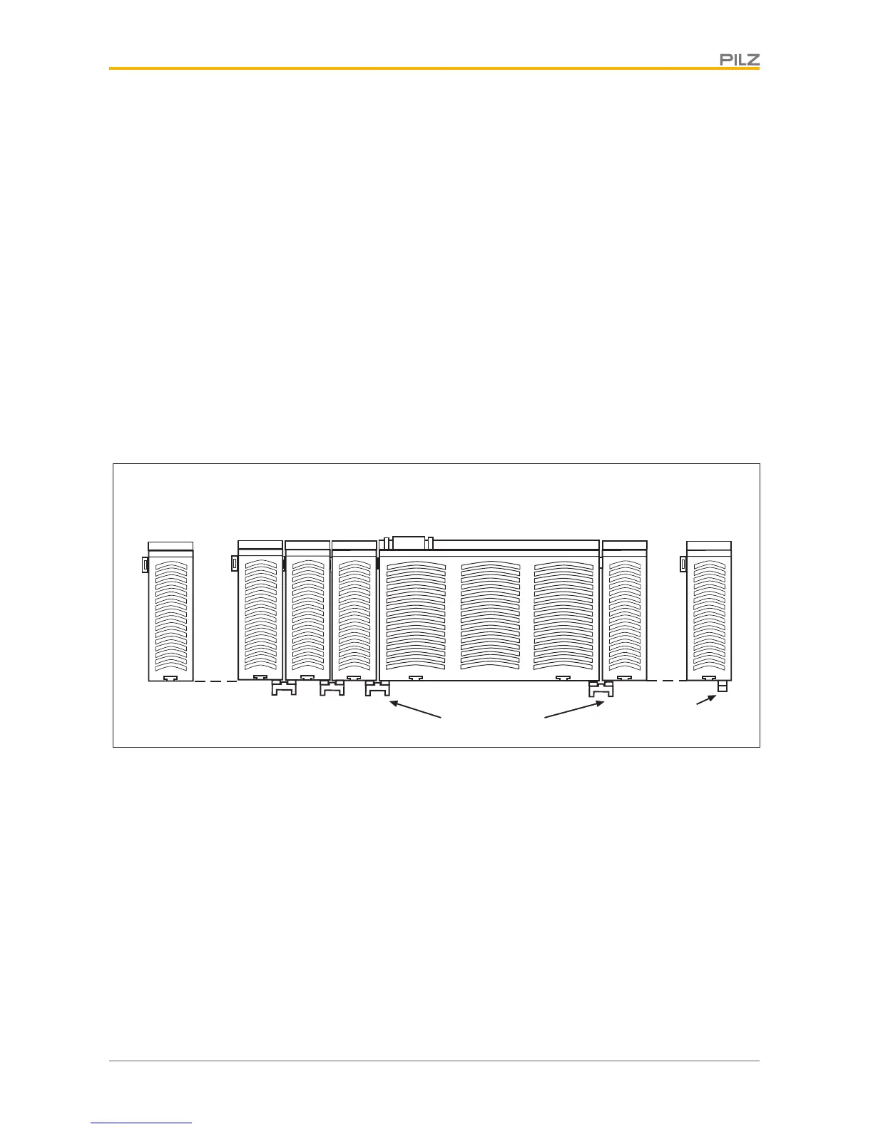
The modules are linked via jumpers.
There are 2 pin connectors on the rear of the base unit.
A max. of 12 expansion modules plus one fieldbus module may be connected to one base
unit.
} Ensure that no terminator is connected.
} Connect the base unit, the expansion modules and the fieldbus module using the jump-
ers supplied.
} The terminator must be fitted to the last expansion module to the right of the base unit.
} A terminator must not be fitted to the last expansion module to the left of the base unit.

 Loading...


