4.1 Unit properties
4 Function description
Pilz GmbH & Co. KG, Felix-Wankel-Straße 2, 73760 Ostfildern, Germany
Telephone: +49 711 3409-0, Telefax: +49 711 3409-133, E-Mail: pilz.gmbh@pilz.de
4-2
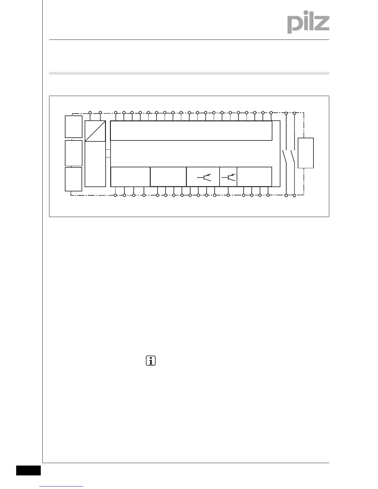
4.1.2.2 Block diagram
Block d iagram4-Blockschaltbild_Basis_RS232+ETH
4.1.2.3 Diagnostics
Diagnostics4-Funktionen_multi_Basis_Diagnose_ETH und RS232
The status and error messages displayed by the LEDs are saved in an
error stack. This error stack can be read from the PNOZmulti Configura-
tor via the interfaces (RS 232 or Ethernet). More comprehensive diag-
nostics are possible via the interfaces or one of the fieldbus modules,
e.g. the PROFIBUS module.
4.1.2.4 Cascading
Cascading4-Funktionen_multi_Basis_Kaskadierung
The cascading inputs and outputs enable several PNOZmulti and
PNOZelog units to be connected in series or as a tree structure.
INFORMATION
Detailed information on these functions and connection exam-
ples can be found in the online help for the PNOZmulti Configu-
rator and in the PNOZmulti technical catalogue.
=
Power
Input
A1 A2
Test pulse
output
I0 I19I1 I2 I3 I8I5
I11
I4 I9 I12 I13 I14 I15 I16 I17I7 I18I6
I10
O4 O5
=
CI+ CI- CO+
CO-
T3T0
O2
O0
24 V 0 V
T2T1
O1
Cascading
OA0
O3
24 V 0 V
Interface
chip card
Interface
fieldbus,
extension
module
Ethernet/
RS 232
Interface
expansion
module
13 23
14 24

 Loading...


