FORCE Series Installation Guide
10 PIMA Electronic Systems
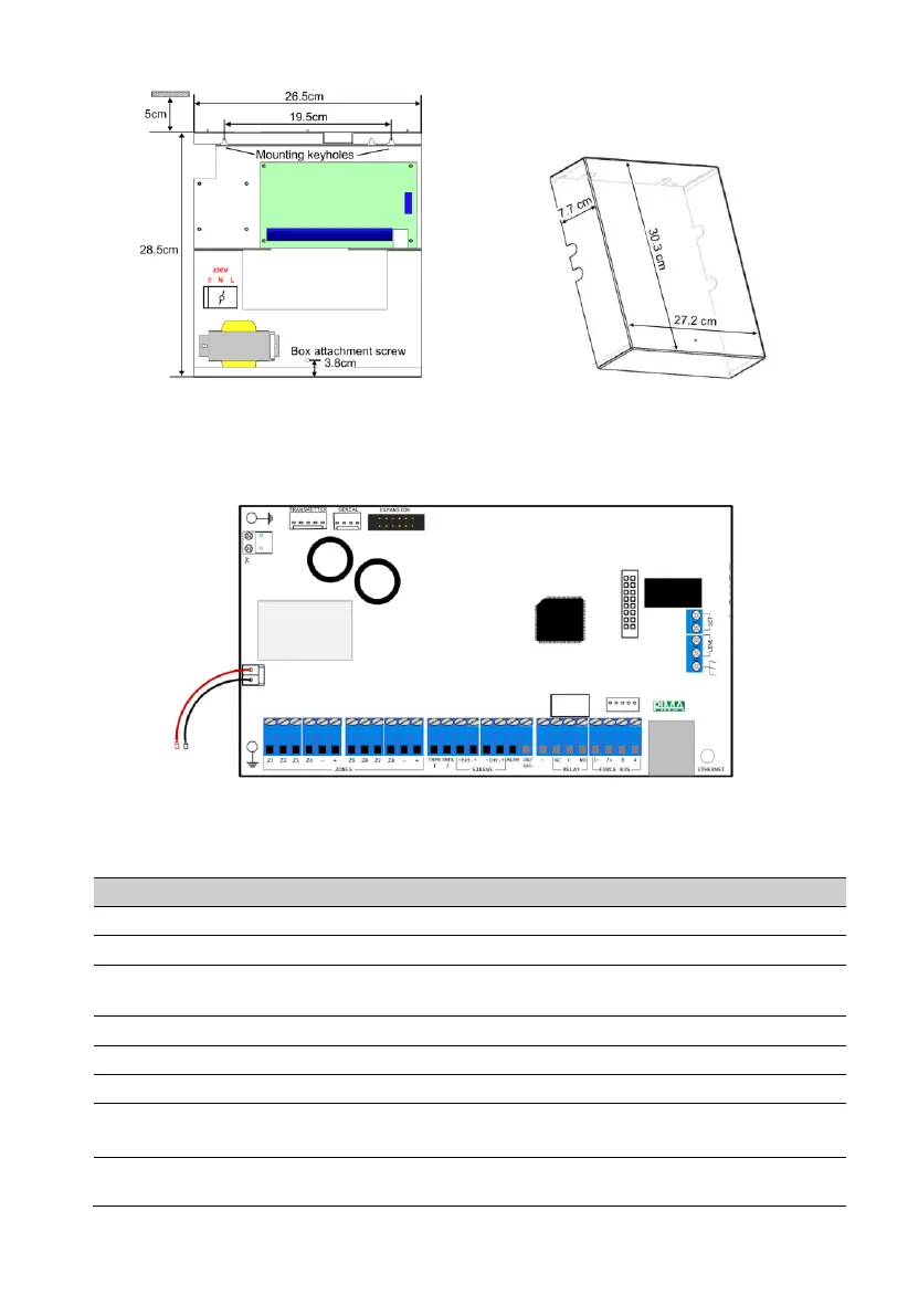
Figure 1. The control panel’s rack
2.3 The control panel’s circuit board
Figure 3. The control panel’s circuit board diagram
Following is a table of the circuit board’s terminals.
Z1-Z8 zones, (+)/(-) detectors’ voltage
Tamper switches 1-2; FORCE Lite/32: TMPR 2 input unavailable.
External/internal sirens, (+)/(-); FORCE Lite/32: the Int. output is
unavailable.
Output (by default, switched to minus at alarm)
Output: (by default, switched to minus on arming)
Output: NC (Normally Close), C (Common), NO (Normally Open);
FORCE Lite: unavailable
The -/+/In/Out terminals are numbered 1-4. All expanders and
keypads have the same wire numbering.
1 2 3 4 5 7 8
11
12
13
14
151617
18
19
6 9
10
 Loading...