Do you have a question about the Pioneer A-105 and is the answer not in the manual?
Warning to prevent fire or shock hazard by keeping the appliance away from rain or moisture.
Caution against opening the unit to prevent risk of electric shock.
Explains the meaning of lightning flash and exclamation point safety symbols.
Details power output specifications for models A-105 and A-205.
Describes the current feedback circuit for improved operating stability.
Ensures high fidelity playback with consistent frequency characteristics and clarity.
Allows dubbing between two cassette decks.
Notes the availability of speaker terminals for two systems on the A-205 model.
Instructions for setting the line voltage selector switch before plugging in the power cord.
Guidance on selecting a well-ventilated location, avoiding high temperatures, humidity, and direct sun.
Ensures adequate space around the unit for heat dissipation to prevent overheating.
Precautions for handling the power cord to prevent electric shock or fire hazards.
Instructions for cleaning the unit's exterior using appropriate cloths and mild cleansers.
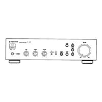
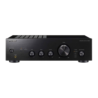
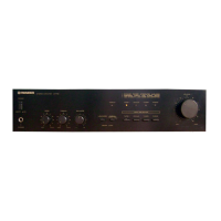
Button to turn the unit's power ON and OFF.
Selects the desired playback source from various inputs like PHONO, CD, TUNER, LINE, TAPE.
Knob used to adjust the audio playback volume level.
Used for adaptor components or cassette decks connected to TAPE 2 MONITOR terminals.
Bypasses tone controls and filters for pure sound reproduction.
Boosts low and high frequencies for listening at low volume levels.
Adjusts the sound balance between left and right speakers.
Adjusts the high-frequency tone response.
Adjusts the low-frequency tone response.
Switches between SPEAKERS A and SPEAKERS B systems for the A-205 model.
Port for connecting headphones, which may mute speaker output.
Terminals for PHONO, CD, TUNER, LINE, and TAPE connections.
Terminals for recording and playback of TAPE 1/DAT and TAPE 2/MONITOR.
Terminals for connecting SPEAKERS A and SPEAKERS B systems (A-205 only).
Socket for connecting the power cord to the AC wall socket.
Component for selecting the appropriate AC input voltage.
Provides switched and unswitched power outlets for connected equipment.
Connects SPEAKERS A system (left/right channels) for A-205 model.
Turntable ground terminal to reduce hum.
Connects speaker systems (left/right channels) for A-105 model.
Diagram showing how to connect a CD player to the unit.
Diagram showing connections for DAT/Cassette decks for playback and recording.
Diagram illustrating the connection of an FM-AM tuner.
Diagram showing how to connect a turntable.
Diagram showing connections for speaker systems to the amplifier.
Identifies CD players, DAT/Cassette decks, adaptor components, and tuners.
Identifies speaker systems A and B for models A-205 and A-105.
Identifies the turntable connection and the AC wall socket connection.
Step-by-step guide on stripping wire and connecting speaker cords to terminals.
Specifies the required speaker impedance for models A-205 and A-105.
Instructions for connecting input/output cords using RCA plugs.
Initial setup steps including power, speaker selection, balance, and switch settings.
Steps to select playback source and adjust volume for listening.
Instructions for selecting recording equipment and starting recording.
Guide on recording from one deck to another for tape copying.
Selecting copying direction using Input Selector and TAPE 2 MONITOR switches.
How to use adaptor components or a cassette deck connected to TAPE 2 MONITOR terminals.
Note on automatic selection of TAPE 1/DAT after power interruption.
Troubleshooting steps for when the unit does not power on.
Steps to diagnose and resolve issues with no sound output.
Steps to fix issues where sound is only from one speaker.
Troubleshooting steps for problems with tape recording or copying.
Detailed specifications for the amplifier section, including power output and distortion.
Specifications for input sensitivity, output level, and frequency response.
Details on tone control range and loudness contour effect.
Specifications for power requirements, outlets, dimensions, and weight.
| Frequency Response | 5Hz-100kHz (+0dB, -3dB) |
|---|---|
| Input Impedance | 47 kOhms (line) |
| Dimensions | 420 x 125 x 337 mm |
| Weight | 6.7 kg |
| Signal to noise ratio: Line | 100 dB |
| Total Harmonic Distortion (20Hz-20kHz, 50W) | 0.08% |
| Power output per channel | 50 Watts |
| Total Harmonic Distortion (THD) | 0.08% |
| Signal-to-Noise Ratio | 100 dB (line) |
| Total harmonic distortion | 0.08% |
| Power Output (8 ohms, 20Hz-20kHz, 0.08% THD) | 50 W |
| Frequency Response (+0dB, -3dB) | 5 Hz to 100 kHz |
| Power Output | 50W per channel (8 ohms, 20Hz-20kHz, 0.08% THD) |