Do you have a question about the Pioneer A-656 and is the answer not in the manual?
Covers fire/shock hazards, moisture, and voltage selector adjustments for regional use.
Guidelines for safe placement, ventilation, heat, power, and cleaning.
Details on polarized plugs, cord protection, and outdoor antenna grounding.
Visual guide for connecting audio sources, tape decks, and speaker systems.
Table of common issues, probable causes, and remedies for operation problems.
Important safety advice for managing and maintaining the power cord.
This document provides comprehensive operating instructions for the Pioneer Stereo Amplifiers A-757 and A-656, designed to ensure proper usage and longevity of the units. The manual emphasizes safety precautions, connection procedures, operational guidelines, troubleshooting tips, and maintenance advice.
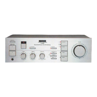
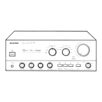
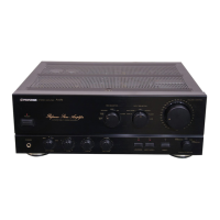
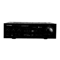
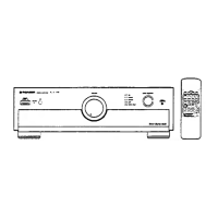
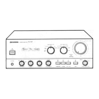
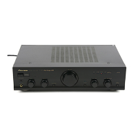
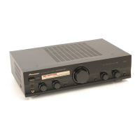
The Pioneer Stereo Amplifiers A-757 and A-656 are high-fidelity audio components designed to amplify audio signals from various sources and deliver them to speaker systems. These amplifiers serve as the central hub for an audio setup, allowing users to connect and manage multiple input devices such as CD players, tuners, turntables, tape decks, video disc players, and VCRs. The primary function is to process and amplify these audio signals, providing a rich and clear sound experience.
The A-757 model, in particular, is highlighted with a robust drive capacity of 150W + 150W/4 Ω (DIN), making it suitable for high-power and low-impedance speaker systems. The A-656 model offers a drive capacity of 120W + 120W/4 Ω (DIN). Both models incorporate a "DIRECT" circuit, which ensures high-fidelity playback by maintaining consistent frequency characteristics and maximizing clarity, bypassing various frequency-adjusting circuits for a purer sound.
A key feature is the built-in phono equalizer, which accommodates both Moving Magnet (MM) and Moving Coil (MC) cartridges, allowing for direct connection of turntables. The A-757 model also includes a PHONO EQ switch/indicator to prevent noise when a phono input is not in use.
The amplifiers are equipped with a "REC SELECTOR" switch, simplifying tape editing and recording processes. This switch allows users to select the recording source independently of the playback source, facilitating flexible recording options, including tape-to-tape copying.
For enhanced sound quality, the amplifiers feature "clean ground technology," which prevents noise from the power line from interfering with the signal ground line, contributing to clean sound reproduction. They also utilize Non-Switching Circuit Type III (A-757) or Type II (A-656) to minimize distortion and achieve high-quality sound.
The design incorporates advanced structural elements such as a Casted Power Transformer (A-757 only), Honeycomb Frame Chassis, and Honeycomb Heat Sink, all contributing to the unit's stability, durability, and efficient heat dissipation, which are crucial for consistent performance.
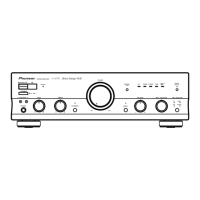
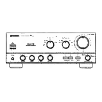
The amplifiers offer a user-friendly interface with various controls and switches for managing audio playback and recording.
Input Selection: The "INPUT SELECTOR" switch allows users to choose among different audio sources like LINE, TUNER, PHONO, CD, DAT/TAPE 1, and TAPE 2. This ensures that the correct input is routed for amplification.
Speaker Management: The "SPEAKERS selector switch" enables users to direct audio to different speaker systems (A, B, or A+B) or to headphones, providing flexibility in listening environments. When using headphones, the switch should be set to "OFF" to mute the speakers.
Volume and Tone Control: A large "VOLUME CONTROL" knob adjusts the overall sound level. "BASS" and "TREBLE" tone controls allow for adjustment of low and high frequencies, respectively, to tailor the sound to personal preferences. These tone controls, along with the "BALANCE" control (for adjusting left/right channel balance) and "LOUDNESS" switch (for boosting low and high frequencies at low volumes), are bypassed when the "DIRECT" switch is engaged, ensuring a pure signal path.
Recording and Copying: The "REC SELECTOR" switch is central to recording operations. It allows users to select a specific source (TUNER, CD, SOURCE) for recording onto a connected tape deck. It also supports tape-to-tape copying (TAPE 1→2 or TAPE 2→1), making it easy to duplicate recordings. The manual provides clear instructions for monitoring while recording, especially with 3-head tape decks.
Adapter Functionality: The "ADPT 1/TAPE 3" and "ADPT 2" terminals (A-757 only) allow for the connection of external audio processors like graphic equalizers. Shorting bars are provided for these terminals and must be removed when an adapter is connected, and reinserted when not in use to maintain signal integrity.
Power Management: The "POWER switch/indicator" turns the unit on and off. The amplifiers also feature "AC OUTLETS" (SWITCHED and UNSWITCHED) on the rear panel, allowing other audio components to draw power directly from the amplifier. The SWITCHED outlets are controlled by the amplifier's power switch, while UNSWITCHED outlets provide continuous power. Users are cautioned against connecting high-power appliances to these outlets to prevent overheating or fire risks.
Safety and Setup: The manual emphasizes initial setup steps, including setting the volume to minimum, turning on the power, selecting speaker outputs, and adjusting balance. It also provides specific instructions for connecting speaker cords, ensuring proper polarity and secure connections to prevent damage.
Troubleshooting: A dedicated troubleshooting section helps users diagnose common issues such as no power, no sound, sound from only one speaker, or recording problems. It offers probable causes and remedies, encouraging users to check connections, switch settings, and other components before seeking professional service.
The manual provides essential guidelines for maintaining the external surfaces of the amplifier to ensure its appearance and longevity.
By adhering to these maintenance instructions, users can help preserve the aesthetic and functional integrity of their Pioneer Stereo Amplifiers.
| Damping Factor | 60 |
|---|---|
| Frequency Response | 5 Hz to 100 kHz |
| Signal to Noise Ratio | 110 dB (Line input) |
| Input Sensitivity | 150mV (line) |
| Dimensions | 420 x 435 x 157mm |