EasyManua.ls Logo

Pioneer A-605R Service Manual

Pioneer A-605R
25 pages
To Next Page IconTo Next Page
Page #1 background imageLoading...
Page #1 background image
C,!)
RIOIMEER*
The Art
of Entertainment
Service
Manual
B’
in
»h(w»
model A-605R.
ORDER
NO.
RRV1
594
STEREO AMPLIFIER
A-605R
A-605R-G
A-505R
A-405R
A-405R-G
THIS
MANUAL
IS
APPLICABLE
TO
THE
FOLLOWING
MODEL(S)
AND TYPE(S).
Type
Model
Power
Requirement
The voltage can
be
converted
by the
following
method.
A-605R A-605R-G A-505R
A-405R A-405R-G
HY/EW
0 0 0 0 O
AC220
-
230V
HY/GR 0
-
0 0
-
AC220
-
230V
SD 0
- - -
AC110V/120
-
127V/220V/240V With the voltage
selector
HV
0
-
-
0
-
AC230V
CONTENTS
1 . EXPLODED VIEWS
AND PARTS LIST
2
2. PACKING AND
PARTS
LIST
5
3.
SCHEMATIC
AND
PCB
CONNECTION
DIAGRAMS
....
6
4. PCB PARTS LIST
21
5. ADJUSTMENTS
24
6.
IC
INFORMATION
25
7.
BLOCK
DIAGRAM
26
8.
FORA-605R/HY/GR,SD, HV,
A-605R-G/HY/EW,
A-505R/HY/EW.
HY/GR, A-405R/HY/EW,
HY/GR,
HV
AND A-405R-G/HY/EW
TYPES
27
9. PANEL FACIRITIES
32
10.
SPECIFICATIONS
35
PIONEER
ELECTRONIC CORPORATION
4
Meguro
i
-Chome,
Meguro-ku, Tokyo
153,
Japan
PIONEER
ELECTRONICS SERVICE,
INC.
P.O.Box
1760,
Long
Beach, CA
90801-1760,
U.S.A.
PIONEER ELECTRONIC lEUROPEl
N.V. Haven
1087,
Keetberglaan
1.
9120
Melsele,
Belgium
PIONEER
ELECTRONICS
ASIACENTRE PTE. LTD.
501 Orchard
Road,
#10-00
Lane
Crawford
Place, Singapore
0923
©
PIONEER ELECTRONIC CORPORATION 1996
T-FFK
APR.
1996
Printed
in
Japan

Other manuals for Pioneer A-605R

Question and Answer IconNeed help?

Do you have a question about the Pioneer A-605R and is the answer not in the manual?

Pioneer A-605R Specifications

General IconGeneral
BrandPioneer
ModelA-605R
CategoryAmplifier
LanguageEnglish

Summary

1. Exploded Views and Parts List

Exploded View and Parts List

Detailed diagram and list of external components for assembly.

2. Packing and Parts List

Packing and Parts List Details

List of items included in the package and their respective part numbers.

3. Schematic and PCB Connection Diagrams

Overall Wiring Diagram

Shows the complete electrical connections between major assemblies.

Assembly Schematics

Detailed circuit diagrams for AF, Front L/Volume, and Front R/Headphone/AC assemblies.

4. PCB Parts List

PCB Component Listings

Comprehensive list of components used on various Printed Circuit Boards.

5. Adjustments

Idle Current Adjustment Procedure

Step-by-step guide to set the idle current for optimal amplifier performance.

6. IC Information

PD5369A Microcomputer IC Details

Pin assignment and function description for the remote control microcomputer IC.

7. Block Diagram

8. Model Specific Parts

A-605R Series Parts and Construction

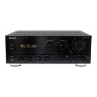
Lists parts and construction differences for A-605R models.

A-505R Series Parts and Construction

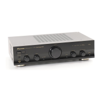
Lists parts and construction differences for A-505R models.

A-405R Series Parts and Construction

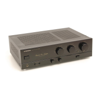
Lists parts and construction differences for A-405R models.

9. Panel Facilities

Front Panel Controls Overview

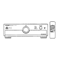
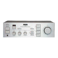
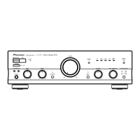
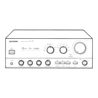
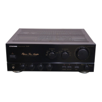
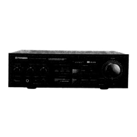
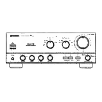
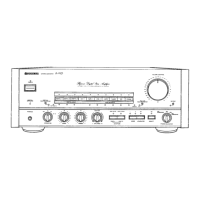
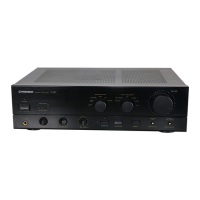
Description of POWER, VOLUME, INPUT SELECTOR, REC SELECTOR, and TAPE 2 MONITOR controls.

Tone, Balance, and Speaker Controls

Explanation of BASS, TREBLE, BALANCE, MUTING, LOUDNESS, and SPEAKER controls.

Headphone Jack and Other Controls

Details on the PHONES jack and SPEAKERS A/B selector functions.

Related product manuals