EasyManua.ls Logo

Pioneer A-676-G User Manual

Pioneer A-676-G
29 pages
To Next Page IconTo Next Page
Page #1 background imageLoading...
Page #1 background image
WY
PIONEER’
The
Art
of
Entertainment
Setvice
ALEVE
om
:
STEREO
AMPLIFIER
A-676-G
..
@
Refer
to
the
service
manual
ARP2240
for
A-676.
@
This
manual
is
applicable
to
A-676-G/HEZ.
©
A-676-G
is
the
same
as
A-676
except
for
color.
CONTRAST
OF
MISCELLANEOUS
PARTS
NOTES:
¢
Part
without
part
number
cannot
be
supplied.
©
The
&\
mark
found
on
some
component
parts
indicates
the
importance
of
the
safety
factor
of
the
part.
Therefore,
when
|
replacing,
be
sure
to
use
parts
of
identical
designation.
©
Parts
marked
by
“®”
are
not
always
kept
in
stock.
Their
delivery
time
may
be
longer
than
usual
or
they
may
be
unavailable.
A-676-G/HEZ
and
A-676/HEWZ
have
the
same
construction
except
for
the
following:
Part
No.
Mark
Symbol
&
Description
Remarks
.
‘A-676/HEWZ
A-676-G/HEZ
Rotary
knob
L
AAB1222
‘AAB1287
Rotary
knob
M
‘AAB1223
AAB1288
Rotary
konb
S
AAB1224
‘AAB1289
Push knob
AAD1536
AAD2287
Direct
knob
‘AAD1560
AAD2288
Power
knob
AAD2010
AAD2302
Name
plate
‘AAM1028
Non
supply
Packing
case
AHD2068
AHD2311
Panel
base
AMB1799
AMB2005
Front
panel
ANB1455,
‘ANB1524
Operating
instructions
arcs
|
ese
(German)
Operating
instructions
=|
nee
ARETI94
(English,
French,
German,
Italian,
Dutch,
Swedish,
Spanish,
Portugues)
Screw
FBT40PO80FZK
FBT40PO80FCR
PIONEER
ELECTRONIC
CORPORATION
=
4-1,
Meguro
1-Chome,
Meguro-ku,
Tokyo
153,
Japan
PIONEER
ELECTRONICS
SERVICE
INC.
P.O.
Box
1760,
Long
Beach,
California
90801
U.S.A.
PIONEER
ELECTRONICS
OF
CANADA,
INC.
300
Allstate
Parkway
Markham,
Ontario
LR
OP2
Canada
PIONEER
ELECTRONIC
[EUROPE]
N.V._
Haven
1087
Keetberglaan
1,
9120
Melsele,
Belgium
PIONEER
ELECTRONICS
AUSTRALIA
PTY.
LTD.
178-184
Boundary
Road,
Braeside,
Victoria
3195,
Australia
TEL:
[03]
580-9911
©
PIONEER
ELECTRONIC
CORPORATION
1992
ra
apn,
oop
bated
titeBor
Question and Answer IconNeed help?

Do you have a question about the Pioneer A-676-G and is the answer not in the manual?

Pioneer A-676-G Specifications

General IconGeneral
Damping Factor60
Input Sensitivity150 mV (Line)
Dimensions420 x 435 x 162mm
Speaker Load Impedance4 Ω to 16 Ω
Frequency Response5Hz-100kHz (+0dB, -3dB)
Signal-to-Noise Ratio110 dB (Line)

Summary

Contrast of Miscellaneous Parts

Notes on Part Replacement and Availability

General notes about part availability, safety marks, and replacement procedures.

Exploded Views and Parts List

Exterior and Packing Parts List

List of external components and packing materials with their part numbers.

Schematic Diagrams

Circuit Assembly Schematics

Diagrams detailing the internal circuitry of major assemblies like Phono, Input Selector, and Tone Amp.

Power Supply and Voltage Selection

SD Type Power Supply Section

Diagram and details specific to the SD type power supply.

Line Voltage Selection Guide

Instructions for changing the unit's voltage setting to match local power.

P.C. Board Connection Diagrams

Power Supply PCB Connections

Visual representation of the PCB layout and connections for the power supply.

PCB Layouts for Key Assemblies

REC OUT, TONE, and PHONO PCB Layouts

Component placement diagrams for REC OUT, TONE AMP, and PHONO AMP circuit boards.

Layouts of Major Circuit Boards

POWER, VR, SPEAKER, HEADPHONE PCB Layouts

Component placement diagrams for POWER, VR, SPEAKER TERM, and HEAD PHONE circuit boards.

Component Lists for Circuit Boards

TONE, SPEAKER, INPUT SELECTOR PCB Parts

Detailed parts list for TONE AMP, SPEAKER SWITCH, and INPUT SELECTOR circuit boards.

Circuit Board Parts Listings

REC OUT and POWER L PCB Parts

Detailed parts list for REC OUT ASSEMBLY and POWER L ASSEMBLY circuit boards.

Additional Circuit Board Parts Lists

POWER R and POWER SUPPLY PCB Parts

Detailed parts list for POWER R ASSEMBLY and POWER SUPPLY ASSEMBLY circuit boards.

Further Circuit Board Parts Details

SPEAKER TERM and PHONO PCB Parts

Detailed parts list for SPEAKER TERM ASSEMBLY and PHONO AMP ASSEMBLY circuit boards.

Final Circuit Board Parts Lists

VR, HEADPHONE, DIODE PCB Parts

Detailed parts list for VR ASSEMBLY, HEAD PHONE ASSEMBLY, and DIODE ASSEMBLY.

Model Variations and Part Differences

Miscellaneous Parts Comparison

Comparison of miscellaneous parts across different model variants (HB, SD, HEWZ, S/HEWZ).

Front Panel Controls and Functions

Power, Phones, and Speaker Selector

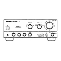
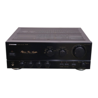
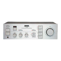
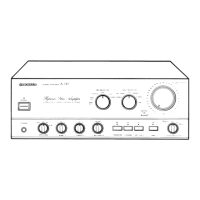
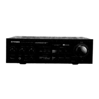
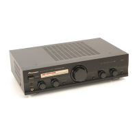
Explanation of the POWER switch, PHONES jack, and SPEAKERS selector switch.

Tone and Balance Controls

Description of the BASS, TREBLE tone, and BALANCE controls.

Additional Front Panel Functions

Loudness, Tape Monitor, and Direct Mode

Details on LOUDNESS, ADPT/TAPE 3, and DIRECT button operations.

Input and Record Selector Operation

How to use the INPUT SELECTOR and REC SELECTOR switches for playback and recording.

Technical Specifications

Power Output and Distortion Ratings

Detailed specifications for power output, THD, and power bandwidth.

Frequency Response and Noise Levels

Specifications for frequency response, tone control range, filters, and signal-to-noise ratios.

Adjustments and Maintenance

Idle Current Adjustment Procedure

Step-by-step guide to adjust the amplifier's idle current.

Related product manuals