ORDER NO.
PIONEER ELECTRONIC CORPORATION 4-1, Meguro 1-Chome, Meguro-ku, Tokyo 153-8654, Japan
PIONEER ELECTRONICS SERVICE, INC. P.O. Box 1760, Long Beach, CA 90801-1760, U.S.A.
PIONEER ELECTRONIC (EUROPE) N.V. Haven 1087, Keetberglaan 1, 9120 Melsele, Belgium
PIONEER ELECTRONICS ASIACENTRE PTE. LTD. 501 Orchard Road, #10-00 Lane Crawford Place, Singapore 0923
PIONEER ELECTRONIC CORPORATION 1998
RRV1935
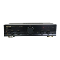
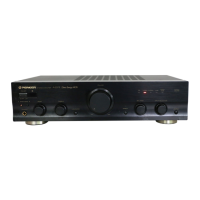
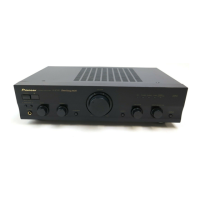
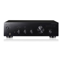
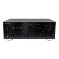
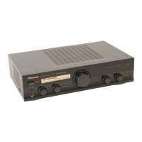
STEREO AMPLIFIER
A-207
1. SAFETY INFORMATION
......................................
2
2. EXPLODED VIEWS AND PARTS LIST
................
3
3. SCHEMATIC DIAGRAM
.......................................
6
4. PCB CONNECTION DIAGRAM
..........................
14
5. PCB PARTS LIST
...............................................
22
6. ADJUSTMENT
....................................................
25
CONTENTS
7. GENERAL INFORMATION
................................
26
7.1 IC
.................................................................
26
7.2 DISASSEMBLY
...........................................
27
7.3 BLOCK DIAGRAM
.......................................
28
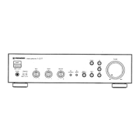
8. PANEL FACILITIES AND SPECIFICATIONS
....
29
THIS MANUAL IS APPLICABLE TO THE FOLLOWING MODEL(S) AND TYPE(S).
Type
Model
A-207
MLXJ
SDXJ
AC220 – 230V
Power Requirement
The voltage can be converted by the
following method.
–––––––
With the voltage selector
T – ZZE APR. 1998 Printed in Japan
AC110V/120 –127V/220V/240V
PHONES
A SPEAKERS B
POWER
OFF ON
STEREO AMPLIFIER
-
–
z¿<?≥
Direct Energy MOS
TAPE 1
/MD
TAPE 2
MONITOR
LINE
TUNER
PHONO
CD
BASS
+
–
TREBLE
+
–
VOLUME
MIN MAX
LOUDNESS DIRECT
BALANCE
R
L
INPUT SELECTOR
TAPE 2
MONITOR