Do you have a question about the Pioneer CDJ-100 and is the answer not in the manual?
Essential precautions for technicians and customers.
Procedure to measure leakage current for safety.
Highlights special safety-related characteristics of parts.
Specifications for the laser diode output.
Additional warnings and precautions related to laser operation.
Overall system block diagram showing major functional units.
Comprehensive wiring diagram showing all connections.
List of all main PCB assemblies with part numbers.
Comprehensive lists of components for various assemblies.
Identifies adjustment items and their physical locations on the PCB.
Lists required adjustment points and cross-references to pages.
Detailed procedure for electrical adjustments, including VCO calibration.
Procedures for diagnosing issues and operating the service mode.
Detailed instructions for disassembly, part replacement, and reassembly cautions.
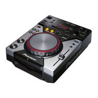
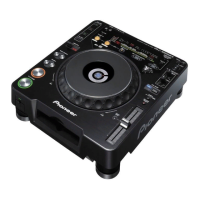
| Frequency Response | 4 Hz to 20 kHz |
|---|---|
| Weight | 4.2 kg |
| Pitch Control | +/- 10% |
| Outputs | RCA |
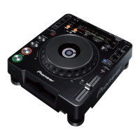
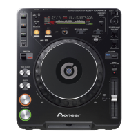
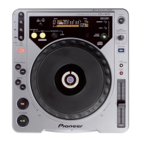
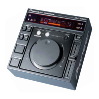
| Type | CD Player |
| Disc Format | CD, CD-R |
| Power Supply | AC 120V |