EasyManua.ls Logo

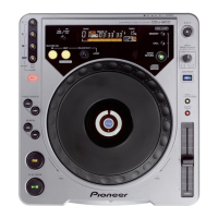
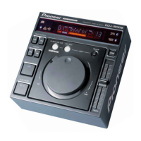
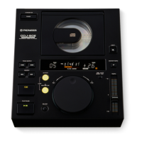
Pioneer CDJ-800 Service Manual

Pioneer CDJ-800
78 pages
To Next Page IconTo Next Page
Page #1 background imageLoading...
Page #1 background image
ORDER NO.
PIONEER CORPORATION 4-1, Meguro 1-chome, Meguro-ku, Tokyo 153-8654, Japan
PIONEER ELECTRONICS (USA) INC. P.O. Box 1760, Long Beach, CA 90801-1760, U.S.A.
PIONEER EUROPE NV Haven 1087, Keetberglaan 1, 9120 Melsele, Belgium
PIONEER ELECTRONICS ASIACENTRE PTE. LTD. 253 Alexandra Road, #04-01, Singapore 159936
PIONEER CORPORATION 2002
CDJ-800
RRV2690
COMPACT DISC PLAYER
CDJ-800
THIS MANUAL IS APPLICABLE TO THE FOLLOWING MODEL(S) AND TYPE(S).
Model Type Power Requirement Remarks
CDJ-800 KUCXJ AC120V
CDJ-800 WYXJ AC220-240V
For details, refer to "Important symbols for good services" .
T-ZZR OCT. 2002 2002 printed in Japan

Other manuals for Pioneer CDJ-800

Questions and Answers:

Pioneer CDJ-800 Specifications

General IconGeneral
Disc TypeCD, CD-R, CD-RW
Frequency Response4 Hz - 20 kHz
Signal-to-Noise Ratio115 dB
Total Harmonic Distortion0.006% (JEITA)
Audio Output Level2.0 V
Power SupplyAC 220-240 V, 50/60 Hz
TypeCD Player
Pitch Control+/- 10%
Outputs1 x RCA stereo pair

Summary

SAFETY INFORMATION

SAFETY PRECAUTIONS

Precautions for customer and service technician safety, including leakage current checks.

PRODUCT SAFETY NOTICE

Notice about special safety characteristics of electrical and mechanical parts.

LABEL CHECK

Additional Laser Caution

Cautions regarding laser interlock mechanism and viewing the objective lens.

IMPORTANT SYMBOLS FOR GOOD SERVICES

Product Safety

Conformity to regulations and maintaining safety during servicing.

Adjustments

Importance of optimum adjustments for product performance.

Cleaning

Proper cleaning for optical pickups, heads, lenses, and mirrors.

Shipping Mode and Screws

Setting shipping mode and installing screws to prevent transit damage.

Lubricants, Glues, Parts

Appropriate use of lubricants, glues, and prescribed replacement parts.

NOTES ON SERVICING

CLEARNING

Cleaning positions and tools before shipping the product.

1. SPECIFICATIONS

1. General System Specs

System type, power requirements, consumption, operating conditions, weight, and dimensions.

2. Audio Section Specifications

Specifications for frequency response, signal-to-noise ratio, and distortion.

3. Included Accessories

List of accessories included with the unit.

2. EXPLODED VIEWS AND PARTS LIST

2.1 PACKING

Exploded view of packing components and associated parts list.

2.2 EXTERIOR SECTION

2.3 CONTROL PANEL SECTION

2.4 SLOT-IN MECHANISM SECTION

3. BLOCK DIAGRAM AND SCHEMATIC DIAGRAM

3.1 BLOCK DIAGRAM

Block diagram illustrating the system architecture and component interconnections.

3.2 OVERALL WIRING DIAGRAM

3.3 MAIN ASSY(1/2)

3.4 MAIN ASSY(2/2)

3.5 AC IN, TRNS, SECB and REGB ASSYS

3.6 MFLB, SLMB and KSWB ASSYS

3.7 JFLB, SLDB and JOGB ASSYS

Waveforms

1/2 MAIN ASSY Waveforms

Waveforms for specific pins of the MAIN ASSY (IC118, IC113, IC110, IC119, IC114).

Voltages

1/2 MAIN ASSY Voltages

Voltage measurements for ICs (IC110, IC112, IC117) on the MAIN ASSY.

4. PCB CONNECTION DIAGRAM

4.1 MAIN ASSY PCB Connections

PCB connection diagram for the MAIN ASSY (Side A and Side B).

4.2 AC IN & TRNS ASSYS PCB

PCB connection diagrams for AC IN and TRNS ASSYS.

4.3 SECB, REGB & SLMB ASSYS PCB

PCB connection diagrams for SECB, REGB, and SLMB ASSYS.

4.4 MFLB & KSWB ASSYS PCB

PCB connection diagrams for MFLB and KSWB ASSYS.

4.5 SLDB, JOGB & JFLB ASSYS PCB

PCB connection diagrams for SLDB, JOGB, and JFLB ASSYS.

5. PCB PARTS LIST

List of Assemblies

List of major assemblies and their part numbers.

MAIN ASSY Semiconductors

List of semiconductors for the MAIN ASSY.

Coils and Filters

List of coils and filters with part numbers.

Capacitors

List of capacitors with part numbers.

Resistors

List of resistors with part numbers.

Others

List of other components with part numbers.

SECB ASSY Semiconductors

List of semiconductors for the SECB ASSY.

REGB ASSY Semiconductors

List of semiconductors for the REGB ASSY.

TRANS ASSY Semiconductors

List of semiconductors for the TRANS ASSY.

KSWB ASSY Semiconductors

List of semiconductors for the KSWB ASSY.

JFLB ASSY Semiconductors

List of semiconductors for the JFLB ASSY.

SLMB ASSY Switches and Relays

List of switches and relays for the SLMB ASSY.

JOGB ASSY Semiconductors

List of semiconductors for the JOGB ASSY.

SLDB ASSY Semiconductors

List of semiconductors for the SLDB ASSY.

6. ADJUSTMENT

7. GENERAL INFORMATION

7.1 DIAGNOSIS

Service modes for diagnostics, including confirmation and version checks.

Button & Display Function Confirmation

Procedure to confirm button inputs and display functions in service mode.

Player Operation Confirmation

Using a remote control to test mechanism and servo system operations.

Version Confirmation Mode

How to confirm software versions of the display and player microcomputers.

5. Error Display List

7.1.2 POWER ON SEQUENCE

PICKUP GOOD OR BAD JUDGEMENT

MAIN ASSY Pickup Check

Methods to judge the condition of the pickup using resistance measurements.

7.1.3 DISASSEMBLY

MAIN Assy Disassembly

Procedure for disassembling the MAIN Assy from the unit.

CD Mechanism Disassembly

Procedure for removing the CD Mechanism assembly.

Control Panel Section Disassembly

Procedure for removing the Control Panel section.

JOG Section Disassembly

Procedure for disassembling the JOG section components.

7.2 PARTS

7.2.1 IC Listing

List of Integrated Circuits (ICs) with part numbers and pin assignments.

8. PANEL FACILITIES

8.1 Front Panel Overview

Overview of the front panel controls and indicators with numbering.

Panel Controls and Indicators

Detailed description of buttons, dials, switches, and their functions.

Display Section Overview

Description of the front panel display elements (Track, Time, Tempo, BPM).

Jog Dial Display Elements

Description of the Jog Dial display elements (Operation, Cue point, Memory, Touch, Vinyl mode).

Related product manuals