YW)
PIONEER’
The
Art
of
Entertainment
ORDER
NO.
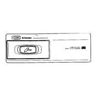
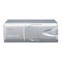
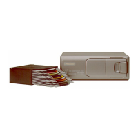
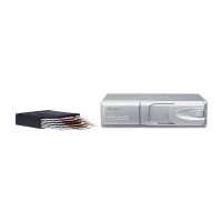
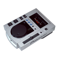
MULTI-COMPACT
DISC
PLAYER
Cc
LD
x
IVI
UC,
EW
COMPACT
DIGITAL
AUDIO
@See
the
separate
manual
CX-612
(CRT1518)
for
the
CD
mechanism
description.
CONTENTS
~
1.
SAFETY
INFORMATION
........escesesesscssesseeseeseceeeenenieee
2
9.
CHASSIS
EXPLODED
VIEW............:ceceeseeeeeneeeteees
51
2.
DISASSEMBLY
.......cccecceecceeesssesecssseneeeeeeeneseenereneesensaes
3
10.
MAGAZINE
ASSY
EXPLODED
VIEW...
54
3.
BLOCK
DIAGRAM
........ceseeeeceeesseeeeeeerenesseseneneseneeneners
5
11.
CD
MECHANISM
UNIT
EXPLODED
VIEW..............
56
A,
ADJUSTMENT
0.0...
ccccececcesseesenesesscseeeseesseeeeeneeeeeeseeeeees
7
12.
PACKING
METHOD.
........ccccscecesseeseeesneeeeenseeeeeeenees
63
5.
CONNECTION
DIAGRAM(1)........::eeseeeeeteeretereeeeeers
39
13.
ELECTRICAL
PARTS
LIST
..........cccscssessseesreetteeetettees
64
6.
SCHEMATIC
CIRCUIT
DIAGRAM(1)........:---seeseeeees
43
14.
CIRCUIT
DESCRIPTION...
cee
ceecceseeseeeeseetereeseeetere
66
7.
SCHEMATIC
CIRCUIT
DIAGRAM(2)........:::eceeeeeeee
46
15.
OPERATIONS
AND
CONNECTION
.........ceseereretees
86
8.
CONNECTION
DIAGRAM(2)........ccccceseseeereetereereeeees
49
SPECIFICATIONS
@CD
Player
Service
Precautions
one
C
di
di
1.Since
these
screws
protects
the
mechanism
during
TSH
eee
ee
ompactdise
audio
system
“transport,
be
sure
to
affix
it
when
its
transported
for
Signal
format
...........-
Sampling
frequency:
44.1
kHz
repair,
etc.
Number
of
quantisation
bits:
16;
linear
2.For
pick-up
unit
handling,
please
refer
to
Power
source
......
14.4
V
DC
(10.8
—
15.6
V
allowable)
“Disassembly”.
During
replacement,
handling
precau-
Ween
pence
taeda
ceecumaiatan
8
kg
(6
Aaa
tions
shall
be
taken
to
prevent
an
electrostatic
dis-
Dimensions.
.............275
(W)
x
93
(H)
x
168
(D)
mm
charge
{protection
by
a
short
pin):
[10-7/8
(W)
x
3-5/8
(H)
x
6-5/8
(D)
in.]
3:During
disassembly,
be
sure
to
turn
the
power
off
since
an
internal
IC
might
be
destroyed
when
a
con-
Audio
i
nector
is
plugged
or
unplugged.
Frequency
characteristics
........
5
—
20,000
Hz
(+1
dB)
Signal-to-noise
ratio
.97
dB
(1
kHz)
(IHF-A
Network)(UC)
97
dB
(1
kHz)
(IEC-A
Network)(EW)
Dynamic
range
.......
00.
cece
eee
ee
eee
ee
94
dB
(1
kHz)
-
Output
level.............
0.
eee
e
eee
500
mV
(1
kHz,
0
dB)
Number
of
channels.............00e
eee
e
eee
ee
2
(stereo)
Note:
Specifications
and
the
design
are
subject
to
possible
modification
without
prior
notice
due
to
improvements.
PIONEER
ELECTRONIC
CORPORATION
4-1,Meguro
1-Chome,Meguro-ku,
Tokyo
153,Japan
PIONEER
ELECTRONICS
SERVICE
INC.
P.O.Box
1760,Long
Beach,California
90801
U.S.A.
PIONEER
ELECTRONICS
OF
CANADA,
INC.
300
Allstate
Parkway
Markham,Ontario
L3R OP2
Canada
PIONEER
ELECTRONIC
[EUROPE]
N.V.
Haven
1087
Keetberglaan
1,9120
Melsele,
Belgium
PIONEER
ELECTRONICS
AUSTRALIA
PTY.LTD.
178-184
Boundary
Road,Braeside,
Victoria
3195,Australia
TEL:{03]580-9911
©
PIONEER
ELECTRONIC
CORPORATION
1993
Sune
ven
eaneainaeen