Do you have a question about the Pioneer CT-W201A and is the answer not in the manual?
| Track System | 4-track, 2-channel stereo |
|---|---|
| Total Harmonic Distortion | 0.8% |
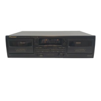
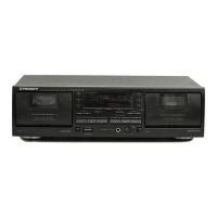
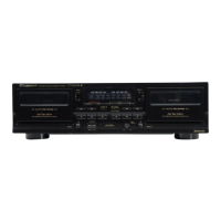
| Type | Double Cassette Deck |
| Motor | DC servo |
| Frequency Response (Normal Tape) | 30Hz to 14kHz |
| Output | 0.5V (line) |
| Inputs | 1 x line |
| Outputs | 1 x RCA |
| Power Supply | 50/60 Hz |
Precautions for service technicians and product safety.
Highlights safety-related characteristics of replacement parts.
Details packing components and their part numbers.
Shows variations in exterior parts for different models.
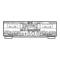
Shows variations in front panel parts for different models.
High-level functional block diagram of the system.
Block diagram for the main unit, showing its internal functions.
Block diagram for the subb unit, showing its internal functions.
Schematic diagram for the first half of the main unit.
Schematic diagram for the second half of the main unit.
Schematic diagram for Mecha Unit 1.
Schematic diagram for Mecha Unit 2.
Schematic diagram for the second half of the main unit.
Schematic diagram for the subb unit.
PCB connection diagram for the main unit.
PCB connection diagram for the main unit.
Lists the part numbers for assembled PCBs.
Compares PCB assemblies across different models.
Lists component part numbers for the main unit.
Lists component part numbers for the subb unit.
Lists component part numbers for the TRN 2 unit.
Lists component part numbers for the power SW unit.
Procedures for mechanical adjustments like door damping.
Procedures for electrical adjustments like playback level.
Head azimuth and playback level adjustment procedures.
Bias oscillator adjustment procedure.
Procedure for adjusting recording bias.
Procedure for adjusting recording level.
Confirms recording frequency response.
Provides information for diagnosing system issues.
Details the sequence of operations during power on.
Lists integrated circuit (IC) components.
Description of the front panel controls and indicators.
Compares miscellaneous parts across different models.
Exploded view diagram of packing components.
Exploded view diagram of exterior components.
Details differences in PCB assemblies for the main unit.
Details differences in PCB assemblies for the power SW unit.
Details differences in PCB assemblies for the TRN 2 unit.
Details differences in PCB assemblies for the subb unit.