EasyManua.ls Logo

Pioneer PD-F1009 Service Manual

Pioneer PD-F1009
60 pages
To Next Page IconTo Next Page
Page #1 background imageLoading...
Page #1 background image
ORDER NO.
PIONEER CORPORATION 4-1, Meguro 1-chome, Meguro-ku, Tokyo 153-8654, Japan
PIONEER ELECTRONICS SERVICE, INC. P.O. Box 1760, Long Beach, CA 90801-1760, U.S.A.
PIONEER EUROPE N.V. Haven 1087, Keetberglaan 1, 9120 Melsele, Belgium
PIONEER ELECTRONICS ASIACENTRE PTE. LTD. 253 Alexandra Road, #04-01, Singapore 159936
PIONEER CORPORATION 2000
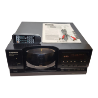
FILE-TYPE COMPACT DISC PLAYER
RRV2262
T–ZZR JAN. 2000 Printed in Japan
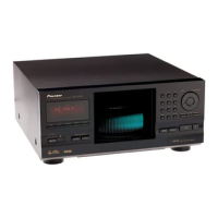
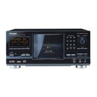
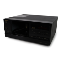
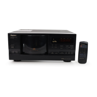
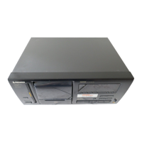
PD-F1009
FILE–TYPE COMPACT DISC PLAYER
MODE
4 1 ¡ ¢
DISC PUSH ENTER
RANDOM
STANDBY
ACCESS
CDF
ILE
CD TEXT
PLAY
OPEN/
CLOSE
UNLOAD
DIRECT LINEAR CONVERSION
STANDBY/ON
SINGLE LOADER
FILE–TYPE CD MECHANISM
Î
CLEAR PROGRAM
DISC TRACK MIN SEC
REPEAT DISPLAY
1-BIT DLC
67
987
0
654
321
TRACKDISC
◊Û¿X,??/
1. SAFETY INFORMATION.................................... 2
2. EXPLODED VIEWS AND PARTS LIST ............. 4
3. BLOCK DIAGRM AND SCHEMATIC DIAGRAM... 14
4. PCB CONNECTION DIAGRAM ....................... 22
5. PCB PARTS LIST ............................................. 38
6. ADJUSTMENT.................................................. 44
7. GENERAL INFORMATION .............................. 48
7.1 DIAGNOSIS ................................................ 48
7.1.1 DISASSEMBL.................................... 48
CONTENTS
THIS MANUAL IS APPLICABLE TO THE FOLLOWING MODEL(S) AND TYPE(S).
Model
PD-F1009
Type
Power Requirement
Remarks
KU/CA AC120V
MY AC220-230V
7.1.2 ERROR CHECK DISPLAY................... 51
7.1.3 EXPLANATION OF DISC DEECTION .. 54
7.1.4 OPERATION FLOWCHART ................ 54
7.2 PARTS .......................................................55
7.2.1 IC ....................................................... 55
7.2.2 DISPLAY ...........................................58
8. PANEL FACILITIES AND SPECIFICATIONS
....................................................... 59
w
w
w
.
x
i
a
o
y
u
1
6
3
.
c
o
m
Q
Q
3
7
6
3
1
5
1
5
0
9
9
2
8
9
4
2
9
8
T
E
L
1
3
9
4
2
2
9
6
5
1
3
9
9
2
8
9
4
2
9
8
0
5
1
5
1
3
6
7
3
Q
Q
TEL 13942296513 QQ 376315150 892498299
http://www.xiaoyu163.com

Other manuals for Pioneer PD-F1009

Questions and Answers:

Pioneer PD-F1009 Specifications

General IconGeneral
Frequency range2 - 20000 Hz
Signal-to-Noise Ratio (SNR)105 dB
CD TextYes
Device typeHiFi CD player
Product colorBlack
I/O portsOptical Digital Output SR (System Remote) Terminal
Dimensions (WxDxH)420 x 433 x 193 mm
Power consumption (typical)12 W
Weight and Dimensions IconWeight and Dimensions
Weight7500 g

Summary

1. SAFETY INFORMATION

1. SAFETY PRECAUTIONS

Checks for customer and technician protection, including leakage current.

2. PRODUCT SAFETY NOTICE

Highlights special safety characteristics of parts and risks of using non-specified replacements.

LABEL CHECK

Additional Laser Caution

Explains laser interlock mechanism and safe viewing practices.

2. EXPLODED VIEWS AND PARTS LIST

2.4 FLOAT BASE ASSY SECTION

How to Install the Disc Table

Instructions on cutting sections and installing the disc table with specific pressure.

3. BLOCK DIAGRAM AND SCHEMATIC DIAGRAM

3.1 BLOCK DIAGRAM

Provides a block diagram showing the interconnections of major assemblies.

3.2 OVERALL WIRING DIAGRAM

OVERALL WIRING DIAGRAM

Illustrates the electrical connections between all major circuit boards and components.

3.3 MECHANISM BOARD, DOOR MOTOR BOARD, DOOR SW BOARD and PICKUP ASSYS

3.4 LOADING SW, LOADING BOARD, SENSOR BOARD, RECIEVE BOARD, RADIATE BOARD and SELECT BOARD ASSYS

3.5 MAIN BOARD ASSY

MAIN BOARD ASSY

Schematic diagram for the main processing and control board.

3.6 MAIN BOARD AND SR BOARD ASSYS

MAIN BOARD AND SR BOARD ASSYS

Schematic diagrams for the main board and the SR (Signal) board.

Waveforms

3.7 DISPLAY BOARD, CONTROL BOARD and POWER BOARD ASSYS

6.1 PREPARATIONS

6.2 ADJUSTMENT PROCEDURES

6.2.1 How to Start/Cancel Test Mode

Explains how to enter and exit test modes for various operations.

6.2.3 Electrical Adjustment

Details procedures for Grating Adjustment and Pickup Radial/Tangential Tilt Adjustment.

3 RF Level Adjustment

Details the procedure for adjusting the RF signal level using an oscilloscope.

4 Disc Detection Adjustment

Explains how to adjust disc detection parameters using a digital multimeter.

7.1.1 DISASSEMBLY

7.1.2 ERROR CHECK DISPLAY

Disc No.: Error Code Details

Provides details on specific error codes related to disc detection and handling.

7.1.3 EXPLANATION OF DISC DETECTION

1. Detection of the rack position

Explains rack position detection using DCNT and DPOS ports.

3-1 In Regard to the Disc Detection Method

Explains disc detection using DCNT and DISC ports and input values.

7.2 PARTS

8. PANEL FACILITIES AND SPECIFICATIONS

SPECIFICATIONS

Related product manuals