Do you have a question about the Pioneer PD-X940M and is the answer not in the manual?
General safety precautions and leakage current check procedure.
Notice regarding special safety characteristics of electrical parts and replacement components.
Cautionary labels for the HEM model regarding laser radiation when the cover is open.
Cautionary labels for the HB model regarding laser radiation when the cover is open.
Important safety notes regarding laser diode operation and interlock mechanisms.
Type, usable discs, signal format, and power requirements for the unit.
Frequency response, S/N ratio, dynamic range, and distortion details.
Specifications for audio line output and headphone jack.
Description of search, programming, repeat, and random play features.
Information on front panel display elements and indicators.
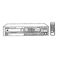
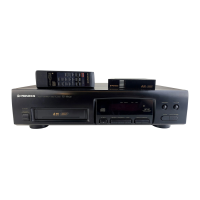
List of accessories provided with the unit, like remote control.
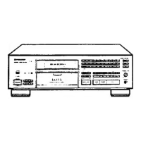
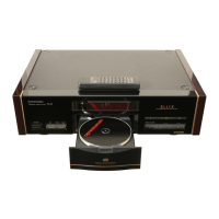
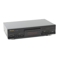
Identification and description of front panel controls and indicators.
Functions of power, eject, play, pause, stop, track search, and random play keys.
How to use program memory, disc selection, and repeat keys.
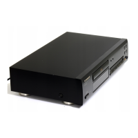
Description of rear panel connections including AC outlet and audio line terminals.
Information on the rear AC outlet, its power limit, and usage precautions.
Instructions for connecting the power cord to the unit or an external power source.
Exploded view and parts list for the exterior components of the unit.
List of parts for the exterior of the unit.
List of parts for the mechanism section of the unit.
Schematic diagram for the pick-up assembly.
Schematic diagram for the main board assembly.
Schematic diagram for the servo mechanism assembly.
Schematic diagram for the select board assembly.
Schematic diagram for the switch board assembly.
Schematic diagram for the power switch board assembly.
Schematic diagram for the transformer board assembly.
Schematic diagram for the function board assembly.
Schematic diagram for the DAC board assembly.
Schematic diagram for the headphone board assembly.
Connection diagram for the power switch board assembly.
Connection diagram for the pick-up assembly.
Connection diagram for the select board assembly.
Connection diagram for the transformer board assembly.
Connection diagram for the main board assembly.
Connection diagram for the servo mechanism assembly.
Connection diagram for the switch board assembly.
Connection diagram for the headphone board assembly.
Connection diagram for the DAC board assembly.
Connection diagram for the function board assembly.
Oscilloscope waveforms for various pins during PLAY MODE operation.
Oscilloscope waveforms for pins during SEARCH and STOP operations.
Oscilloscope waveforms for other play-related signal points.
Oscilloscope waveforms for specific IC pins during various operations.
Oscilloscope waveforms showing power status during POWER ON and OFF.
Visual representations of components and their external appearances.
Lists of PCB assemblies, AC outlets, cords, and other miscellaneous parts.
Detailed lists of semiconductors, capacitors, and resistors with part numbers.
Lists of switches, resonators, and delay lines with part numbers.
Detailed lists of capacitors, semiconductors, and resistors for various board assemblies.
Lists of semiconductors, switches, capacitors, and resistors for Function and DAC Boards.
Lists of switches, semiconductors, capacitors, and resistors for Switch and Select Boards.
List of adjustment and check items to be performed on the unit.
Description of Test Mode setting, cancellation, and key functions.
Identification of adjustment potentiometers (VRs) for various settings.
Example sequences for operations within Test Mode.
Table detailing key functions and their operations during Test Mode.
Procedure to adjust tracking, focus, and RF offsets using potentiometers and oscilloscope.
Procedures for adjusting RF level and confirming laser diode output power.
Procedure to confirm focus lock and spindle lock using a test disc and oscilloscope.
Procedure to adjust grating using the tangential adjustment screw and oscilloscope.
Procedure to adjust tracking balance by eliminating DC component from tracking error signal.
Procedure to adjust tangential alignment for optimal eye pattern clarity.
Procedure to adjust focus gain volume for a horizontal circle Lissajous figure.
Procedure to adjust tracking gain volume for a horizontal circle Lissajous figure.
Procedures for adjusting VCO frequency and confirming S character.
Procedure to adjust MSB for Lch and Rch audio output waveforms to a sine wave.
Notes on miscellaneous parts and differences for the HB type compared to HEM type.
Schematic diagram specifically for the HB type of the unit.
Steps to change the line voltage selection for HEM and HB types.
| Type | CD Player |
|---|---|
| Frequency Response | 2Hz - 20kHz |
| Output Level | 2.0V |
| Disc format | CD |
| Digital outputs | Optical |
| Channels | 2 |
| Output Voltage | 2V |