The system clock 27MHz must be stable during the System Reset or the Power On Reset.
However, if X-TAL is defective, the clock may not become stable until RESET is released.
To check reset timing, turn the main power off and back on, and check if the following waveform is maintained.
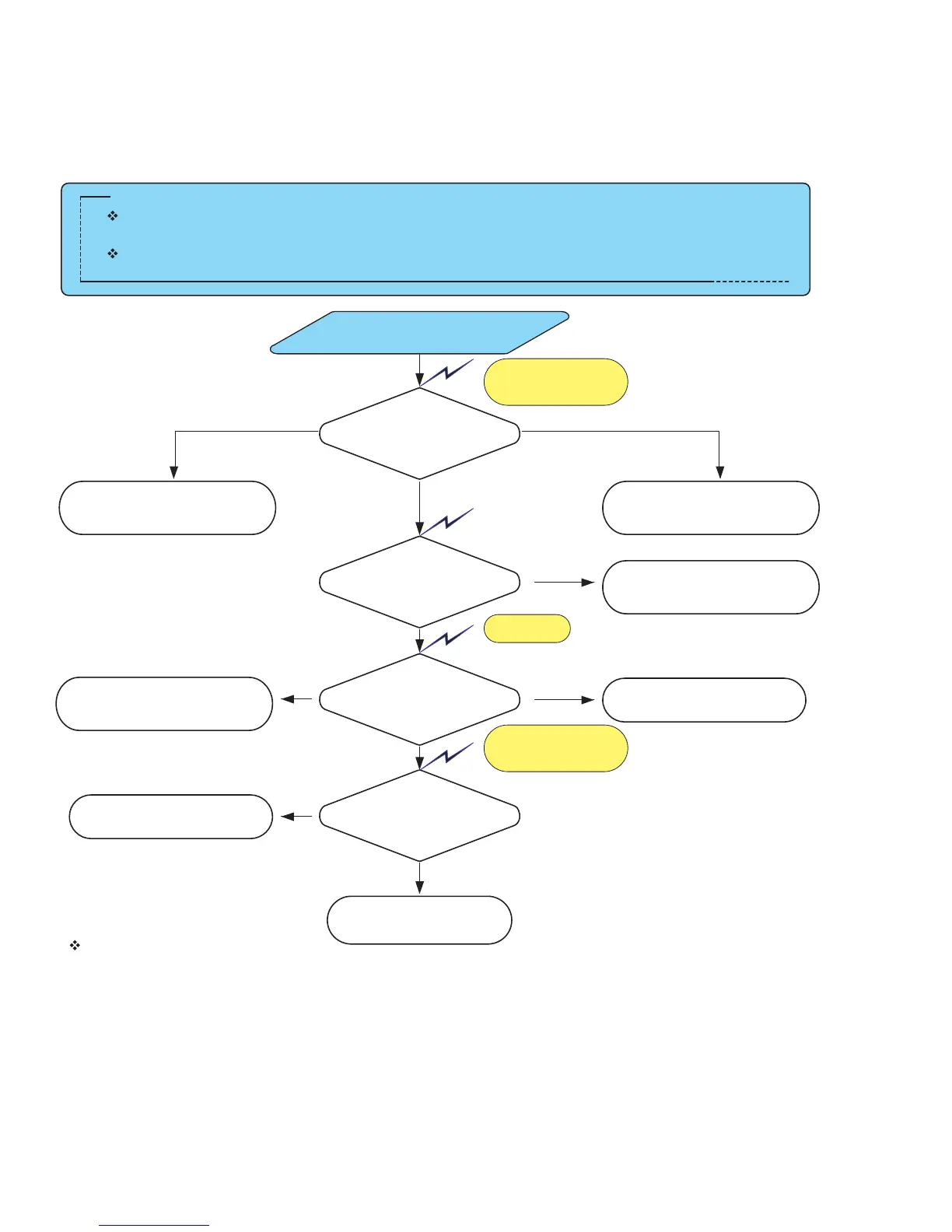
Basic Inspection
Does Not Boot after Power-On or System Reset
Preliminary Checkpoints
Useful Tips
1. The CPU have two 12C for system controller.
One is communicate with system 12C(TDA10046) and the other is communicate with serial EFPROM for storing data.
2. When the system will not operate even though the basic inspection results were normal, check Flash Memory which
contains channel data and program contents.
3. Additionally check for Local DATA and Local ADDRESS buses between CPU and Flash Memory.
4. When replacing parts, be careful of static changes from the tip of the solder iron that can easily damage the parts.
Also, check for assembly condition, soldering condition, or for incorrect or reverse insertion of parts.
5. If the problems are caused by CPU, change CPU board and download Serial Number.
Check the Reset and
clock timing of CPU
Does Not Boot after
System/Power-On Reset
Check the 12C Line
(Pin 6, 5 of U31)
Check for other defective
modes
27 MHz Clock problemReset timing promlem
OK
Check the communication
between DTT and
digital board
Check the soldering status
of JP282.
Check the digital board
Check the soldering status
of X-TAL(Y261) and U261
Check the reset signal of
Flash and Pin1 of U281
NG
OK
Check Flash Memory
Check the waveform CS
and OE of Flash Memory
NG
Check the soldering status
of U40(Flash Memory)
and U62
NG
Check the soldering state of
EFPROM
NG
OK
OK
Waveform 5
Waveform 6
Ch1:SLC, Ch2:SDA
Waveform 2
Waveform 4

 Loading...