C
Candice SilvaAug 13, 2025
What to do if key input is not effective on Pioneer PDP-434PU?
- LLindsey MitchellAug 13, 2025
If the key input is not effective, check the connection of the system cables.
What to do if key input is not effective on Pioneer PDP-434PU?
If the key input is not effective, check the connection of the system cables.
What to do if the power is interrupted, and the red and green warning indications appear on the screen of Pioneer Monitor?
If the power is interrupted and the red and green warning lights appear, check if the system cables are securely connected.
Why Pioneer PDP-434PU Monitor has no power and both red and green LEDs are lit?
If there is no power and both red and green LEDs are lit, check if the TRAP switch is properly set.
Why Pioneer Monitor power is (sometimes) interrupted?
If the power is sometimes interrupted, check if the unit works properly when detection of the TRAP switch is canceled.
How to fix Pioneer Monitor with no power (both red and green LEDs unlit)?
If there is no power and both red and green LEDs are unlit, check if the connection between the POWER SUPPLY and PANEL IF assemblies is properly made.
Why Pioneer PDP-434PU Monitor has no power (green LED not lit)?
If there is no power and the green LED is not lit, check if the FPC is broken or not securely inserted.
What to do if there is abnormality in a one-eighth area of the screen of Pioneer PDP-434PU Monitor?
Check if an abnormal area in the screen changes when the FPC connected to the address corresponding to the abnormal area is replaced with the one corresponding to the next address.
What to do if Pioneer PDP-434PU has abnormal screen (Data of every other dot are abnormal)?
Check that an abnormal area in the screen does not change when the FPC connected to the address corresponding to the abnormal area is replaced with the one corresponding to the next address.
Important safety guidelines for servicing the unit and handling components.
Procedures for checking AC leakage current using cold and hot methods, including AC leakage test.
Identifies areas with electric shock risk from AC power and high voltages.
Explains symbols indicating adjustments, cleaning, shipping, and part replacement procedures.
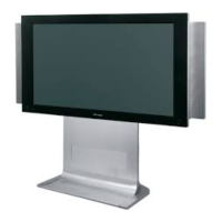
Details technical specifications for the 43" Plasma Display and lists included accessories.
Illustrates the packing configuration for different models of the plasma display.
Exploded view and parts list for the first chassis section of the unit.
Exploded view and parts list for the second chassis section of the unit.
Exploded view of the flame section components, including screws and cables.
Exploded view of the multi base section components, showing screws and connector locations.
Rear view of the unit, labeling the chassis and grip components.
Exploded view of the front panel components, including LED assy and cushion parts.
Parts lists for PDP Service Assy and Panel Chassis Assy components.
High-level block diagram illustrating the main modules and their interconnections.
Detailed block diagram for the 43 Y Drive Assy, showing signal flows and IC connections.
Detailed block diagram for the 43 X Drive Assy, illustrating signal paths and component interactions.
Block diagram of the Panel IF Assy, detailing signal processing and interface connections.
Lists voltages for Power Supply Unit and Media Receiver interfaces.
Lists signal names, I/O types, descriptions, and voltages for the Digital Video Assy.
Displays oscilloscope waveforms for various signals within the Digital Video Assy.
Displays oscilloscope waveforms for various signals within the Panel IF Assy.
Waveforms for drive output signals from X, Y, and Scan assemblies.
Waveforms for the ADR Resonance Block in video and PC modes, showing signal outputs.
Parts list for major assemblies and ADR Logic/Resonance Blocks.
Parts list for 43 Scan A/B Assys and Panel IF Assy components.
Parts list for TMDS RX Block, Panel LED/Key Assys, and Digital Video/UCOM modules.
Parts list for Sus, Y Logic, Y Sus, Y Resonance, and DD Con Blocks.
Parts list for semiconductors, capacitors, resistors, and other components of the HD Audio Amp Assy.
Details adjustments needed when the 43 X Drive Assy is repaired or replaced.
Explains control using RS232C commands via a PC and special device.
Comprehensive list of RS232C commands and their functions for unit control.
Details data formats for GAJ and GPD RS232C commands related to ABL and power-down logs.
Details how to retrieve power-down, white-balance, software version, and unit status via commands.
Illustrates the location of various PCBs within the unit for diagnostic purposes.
Interprets LED status for shutdown and power-down events to identify abnormalities.
Identifies abnormal locations by the number of LED flashes during shutdown and power-down.
Analyzes the shutdown signal system and diagnoses faults based on LED indicators and block diagrams.
Analyzes the power-down signal system and diagnoses faults based on LED flash counts.
Identifies specific defective parts and points to check for power-down issues based on circuit analysis.
Instructions on how to access the Factory mode using the remote control unit.
Guide to interpreting power-down and shutdown logs accessed via Factory mode.
Displays current temperature data from the Panel Sensor Assy and provides conversion formula.
Details symptoms, error indications, pin checks, PD/SD status, and conditions for Panel IF Assy issues.
Details symptoms, error indications, pin checks, and possible defective parts for Digital Video Assy issues.
Procedures to deactivate or cancel the TRAP switch detection mechanism.
Describes modes for operating the unit without a Media Receiver connection.
Explains the temperature compensation for DRIVE-system voltage to improve yield.
Procedures for backing up and restoring adjustment values via EEPROM.
Step-by-step guide for adjusting white balance using RS232C commands and a color meter.
Table diagnosing abnormalities other than shutdown/power-down by symptom, cause, and possible defective parts.
Step-by-step instructions for removing the rear and front cases of the unit.
Instructions for removing the front chassis VL and VR assemblies, including notes on reassembly.
Steps for removing 43 Scan A/B and X Connector A/B assemblies.
Steps for removing the multi base section and its associated connectors.
Details on Comparator, OP-AMP, I2C Bus, Focus/SRS ICs, including pin arrangements and block diagrams.
Block diagram and pin functions for the BA8274F I2C Bus Interface IC.
Pin arrangement and block diagram for the NJM2195L Focus and SRS IC.
Block diagram and functions of the MBM29PL160BD Flash Memory IC.
Pin arrangement and block diagram for the SII169CTG100 Receiver IC.
Block diagrams for PDP Mask Module ICs (STK795-510/511) and Power Amp IC (LA4625).
Pin functions for PDP UCOM IC (M30626FHPGP) and detailed pin functions for PDP ASIC IC (PD5856A) parts 1-10.
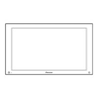
Identifies and describes the front panel buttons, indicators, and remote control sensor.
Identifies rear panel terminals for system cables, speakers, and AC input.
| Screen Size | 43 inches |
|---|---|
| Resolution | 1024 x 768 pixels |
| Display Type | Plasma |
| Brightness | 1000 cd/m² |
| Aspect Ratio | 16:9 |
| Viewing Angle | 160 degrees |
| Input Ports | HDMI, Component, Composite, S-Video |