ORDER NO.
PIONEER CORPORATION 4-1, Meguro 1-chome, Meguro-ku, Tokyo 153-8654, Japan
PIONEER ELECTRONICS (USA) INC. P.O. Box 1760, Long Beach, CA 90801-1760, U.S.A.
PIONEER EUROPE NV Haven 1087, Keetberglaan 1, 9120 Melsele, Belgium
PIONEER ELECTRONICS ASIACENTRE PTE. LTD. 253 Alexandra Road, #04-01, Singapore 159936
PIONEER CORPORATION 2004
ARP3226
T – ZZY SEPT. 2004 Printed in Japan
THIS MANUAL IS APPLICABLE TO THE FOLLOWING MODEL(S) AND TYPE(S).
Model
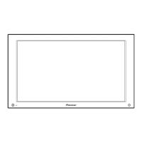
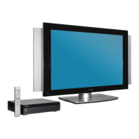
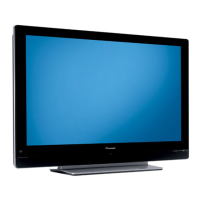
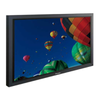
PDP-435PG
Type
Power Requirement
Remarks
TLDPFR
PDP-435PG
‡
AC110 - 240V
PLASMA DISPLAY
¶ This service manual should be used together with the following manual(s):
Model No. Order No. Remarks
PDP-435PE/ WYVI ARP3211 SAFETY INFORMATION, EXPLODED VIEWS AND PARTS LIST , BLOCK DIAGRAM,
PCB PARTS LIST, ADJUSTMENT, IC INFORMATION etc.