PDP-508XG
9
5678
56
7
8
C
D
F
A
B
E
Structure of Layers in Service Factory Mode
INFORMATION mode
1. VERSION (1) The software versions for each microcomputer
2. VERSION (2) The Flash memory versions for each device
3. MAIN NG The shutdown message ID/event times
(Going Clear mode by [ENTER/SET] key)
3-1. CLEAR
Select Yes by [l] key, l pressing and hold [ENTER/SET] key
4. TEMPERATURE The temperature/FAN rotating status/Room light sensor
5. HOUR METER The HOUR METER/P-COUNT information
6. HDMI SIGNAL INFO 1 The information of HDMI information files
7. HDMI SIGNAL INFO 2 The information of HDMI information files
8. VDEC SIGNAL INFO 1 The signal information of VDEC
9. VDEC SIGNAL INFO 2 The signal information of VDEC
PA NEL FACTORY mode Refer to [PANEL FACTORY MODE]
OPTION mode
1. EDID WRITE MODE For factory use
2. CH PRESET For production line use
3. AFT For factory use
4. SYNC DET For technical analysis
INITIALIZE mode
1. SIDE MASK LEVEL For factory use
1-1. SIDE MASK LEVEL
2. FINAL SETUP Set to Factory default settings (it should perform after
2-1. DATA RESET replacing a MAIN Assy)
3. Wide XGA AUTO For technical analysis
Quick Reference upon Service Visit 2
Mode transition and structure of layers in Service Factory mode
Structure of Layers in Panel Factory Mode 1
1. PANEL INFORMATION Version indication of the panel
2. PANEL WORKS Indications of the accumulated power-on time, pulse-meter
count, and power-on count of the panel
3. POWER DOWN Indication of the Power-down history
4. SHUT DOWN Indication of the Shutdown history
5. PANEL-1 ADJ (+)
1. VOL SUS
2. VOL OFFSET
• • • • •
8. VOL YNOFS4
9. RESET1ST_KSB
10. RESET2ND_KSB
• • • • •
23. YSTL_FMR_HZ
24. SUS FREQ
6. PANEL-2 ADJ (+)
1. R-HIGH
2. G-HIGH
3 .B-HIGH Parameters for the WB adjustment of the panel, which are
4. R-LOW required during adjustment after panel replacement
5. G-LOW
6. B-LOW
7. ABL Setting of the power consumption. A setting table is
availab
le for each vertical signal.
To "Structure of Layers in Panel Factory Mode 2"
Structure of Layers in Panel Factory Mode 2
7. PANEL FUNCTION (+)
1. R-LEVEL
2. G-LEVEL
3. B-LEVEL
4. ADDRESS L1 Items for use by engineers
5. ADDRESS L2
• • • • •
11. ADDRESS U4
12. STK MODE
8. ETC (+)
1. BACKUP DATA For transferring backup data (after replacement of
the DIGITAL Assy)
2. DIGITAL EEPROM To clear data of the digital video
3. PD INFO.
4. SD INFO. For clearance of data for the corresponding items.
5. HR-MTR INFO. The clearing method is the same: Select "CLEAR",
6. PM/B1-B5 using [l], then hold [ENTER/SET] pressed for at
7. P COUNT INFO. least 5 seconds. After clearance is completed, {ETC}
8. MAX TEMP. is automatically selected.
9. RASTER MASK SETUP (+)
1. MASK OFF
2. RST MASK 01 For use while Raster Mask (full mask) is displayed.
• • • • • Use [i] or [j] to select the type of mask.
26. RST MASK 25
10. PATTEN MASK SETUP (+)
1. MASK OFF
2. PTN MASK 01 For use while Pattern Mask is displayed. Use [i] or
• • • • • [j] to select the type of mask.
50. PTN MASK 49
11. COMBI MASK SETUP (+)
1. MASK OFF
2. CMB MASK 01 For use while Combination Mask is displayed.
• • • • • Use [i] or [j] to select the type of mask.
1
8. CMB MASK 17
INFORMATION mode
1. VERSION (1)
2. VERSION (2)
3. MAIN NG
4. TEMPERATURE
5. HOUR METER
6. HDMI SIGNAL INFO1
7. HDMI SIGNAL INFO2
8. VDEC SIGNAL INFO1
9. VDEC SIGNAL INFO2
PA NEL FACTORY mode
1. PANEL INFORMATION
2. PANEL WORKS
3. POWER DOWN
4. SHUT DOWN
5. PANEL-1 ADJ
6. PANEL-2 ADJ
7. PANEL FUNCTION
8. ETC.
9. RASTER MASK SETUP
10. PATTEN MASK SETUP
11. COMBI MASK SETUP
INITIALIZE mode
1. SIDE MASK LEVEL
2. FINAL SETUP
3. Wide XGA AUTO
OPTION mode
1. EDID WRITE MODE
2. CH PRESET
3. AFT
4. SYNC DET
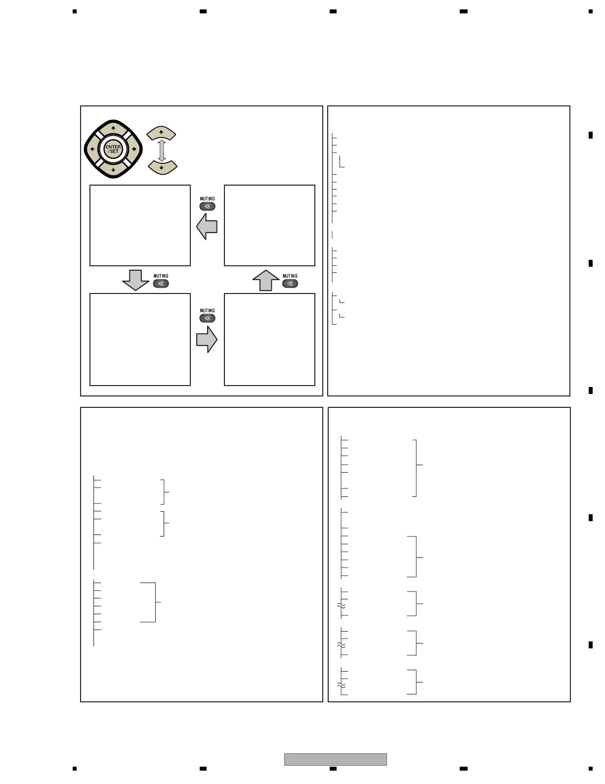
Up
Down
• To shift to another mode, press [MUTING].
• To shift to another item in a specific mode,
press [i] or [j].
• To shift to the next nested layer below for an
item with a "(+)" indication, press [ENTER/SET].
To return to the next nested layer above,
also press [ENTER/SET].
Mode transition in Service Factory mode
For AM noise prevention (Depending on the mode,
brightness of the screen changes.)
For confirmation of the result of the setting change,
the unit must be turned off then back on again.
Modification not required because these items
are basically for factory presetting
Settings required after replacement of the panel

 Loading...