Do you have a question about the Pioneer SR-303 and is the answer not in the manual?
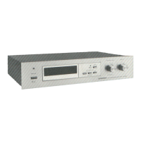
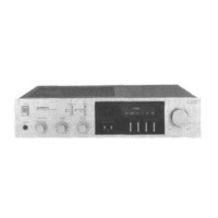
Details the power switch and indicator light on the front panel.
Explains reverb time, depth controls, and related switches/indicators.
Describes tape monitor switch and indicator functions.
Lists and describes all input and output connection jacks on the rear.
Details the attenuator switch and AC outlet functions.
Explains the BBD technology and its operational principles for delay.
Outlines features like single delay, echo, and dynamic delay.
Describes the signal mixing circuit, buffer, LPF, and HPF stages.
Details the BBD IC and the clock generator circuit.
Explains the Voltage Controlled Amplifier and subsequent mixing stages.
Covers circuits for detecting stereo components and driving indicators.
Instructions for removing the top cover and front panel.
Steps for detaching the bottom plate of the unit.
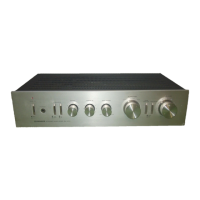
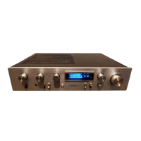
Identifies components on the front panel and with panel removed.
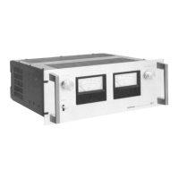
Locates parts on the top and rear views of the unit.
Lists miscellaneous parts and shows external views of transistors/ICs.
Lists semiconductors, capacitors, switches, resistors, and others.
Details parts for lamp, switch, and LED assemblies.
Lists packing case, pads, instructions, and connection cord.
Guides on attaching rack mount adaptors for EIA installation.
| Type | Reverberation Amplifier |
|---|---|
| Total Harmonic Distortion | 0.05% |
| Input Sensitivity | 150 mV |
| Output Level | 150 mV |
| Signal-to-Noise Ratio | 80 dB |