EasyManua.ls Logo

Pioneer SR-60 User Manual

Pioneer SR-60
14 pages
To Next Page IconTo Next Page
Page #1 background imageLoading...
Page #1 background image
0)
PIONEER’
Service
CIRCUIT
DESCRIPTIONS
4
ee
i
ORDER
NO.
=
cee‘
ARP-445-0
REVERBERATION
AMPLIFIER
R-6GO
MODEL
SR-60
COMES
IN
ISX
VERSIONS
DISTINGUISHED
AS
FOLLOWS:
:
HEM
AC
220V,
240V
(switchable)
HB
AC
220V,
240V
(switchable)
Ss
AC
110V,
120V,
220V,
240V
(switchable)
S/G
AC
110V,
120V,
220V,
240V
(switchable)
©
This
service
manual
is
applicable
to
the
S
and
S/G
types.
For
servicing
of
the
other
types,
please
refer
to
the
additional
service
manual.
@
Ce
manuel
d’instruction
se
refére
au
mode
de
réglage,
en
frangais.
@
Este
manual
de
de
servicio
trata
del
método
de
ajuste
escrito
en
espaiiol.
CONTENTS
1.
SPECIFICATIONS
.................-00-
2
8.
BLOCK
DIAGRAM
.............0000
cee
16
2.
FRONT
PANEL
FACILITIES.............
3
9.
ADJUSTMENT
..........
0.000
cee
een
18
3.
PARTS
LOCATION...............00005
5
9
REGLAGE
245.50
c8ced
eens
hos
cawaed
dee
18
4.
EXPLODED
VIEW
.................-00.
6
#9.
AJUSTE
22
dMtiveactee
Shee
hee
eh
Ghanete
ds
18
5.
P.C.BOARDS
CONNECTION
DIAGRAM.....
9
10.
PACKING
............
0000
eee
eee
eae
19
6.
SCHEMATIC
DIAGRAM
................
11
11.
SAFETY
INFORMATION
...............
20
7.
ELECTRICAL
PARTS
LIST..............
14
PIONEER
ELECTRONIC
CORPORATION
4-1,
Meguro
1-Chome,
Meguro-ku,
Tokyo
153,
Japan
PIONEER
ELECTRONICS
(USA)
ING.
P.O.
Box
1760,
Long
Beach,
California
S0801
U.S.A.
PIONEER
ELECTRONIC
[EUROPE]
N.v.
Keetberglaan
1,
2740
Beveren,
Belgium
®IONEER
ELECTRONICS
AUSTRALIA
PTY.
LTD.
178-184
Boundary
Road,
Braeside,
Victoria
3195,
Australia
FA
©
NOV.1983
Printed
in
Japan
Question and Answer IconNeed help?

Do you have a question about the Pioneer SR-60 and is the answer not in the manual?

Pioneer SR-60 Specifications

General IconGeneral
BrandPioneer
ModelSR-60
CategoryAmplifier
LanguageEnglish

Summary

Specifications and Furnished Parts

Miscellaneous Specifications

Details on power requirements, consumption, dimensions, and weight.

Furnished Parts

Lists items included in the product packaging.

Front Panel Facilities

Front Panel Controls and Indicators

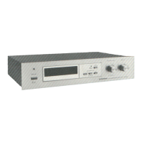
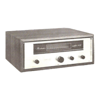
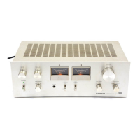
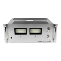
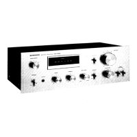
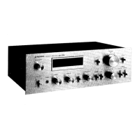
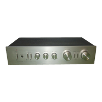
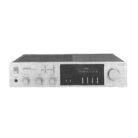
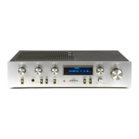
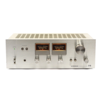
Detailed explanation of all switches, indicators, and controls on the front panel.

Parts Location and Exploded View

Component Layout Diagrams

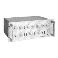
Diagrams showing the location of components on the top, front, and rear panels.

Parts Identification Guide

Visual guide to identify all components within the unit.

PC Boards Connection Diagram

Circuit Board Connectivity

Diagram detailing the interconnections between various PC boards.

Schematic Diagram

Circuit Schematics and Notes

Detailed circuit diagrams with important notes on component usage and variations.

External Appearance of Transistors and ICs

Electrical Parts List

Component Ordering Information

Guidelines for ordering resistors and identifying fast-moving parts.

Block Diagram

Functional Block Overview

Visual representation of the main functional blocks and signal flow.

Signal Path and Adjustments

Signal Path Diagrams

Illustrates signal flow through the amplifier under different switch settings.

Adjustment Procedures

Step-by-step guide for calibrating the unit using specific test points.

Packing and Safety Information

Product Packing Details

Lists the components included in the product packaging for shipping.

Safety Precautions and Notices

Essential safety checks, leakage current testing, and product safety notices.

Related product manuals