Do you have a question about the Pioneer SX-1980 and is the answer not in the manual?
Technical details on transistors, ICs, and diodes used in the receiver.
Specifications for continuous power output and harmonic distortion.
Input impedance and sensitivity for phono and auxiliary inputs.
Sensitivity, selectivity, and signal-to-noise ratio for FM reception.
Sensitivity, selectivity, and signal-to-noise ratio for AM reception.
Power requirements, consumption, dimensions, and weight of the unit.
List of accessories included with the receiver.
Function of the 15Hz and 8kHz filter buttons for audio signal processing.
Controls for selecting speaker outputs (A, B, C) on the rear panel.
Instructions for connecting headphones to the front jack.
Explanation of the receiver's power switch operation.
Details on the tone control switch functionality.
Instructions for adjusting bass and treble frequencies.
Explains the function selection buttons for input sources.
Note regarding the memory marker functionality for tuning.
Operation of the tape monitor switches for recording/playback.
Description of the tape duplicate switch for copying tapes.
How to connect auxiliary audio sources to the receiver.
Connection and use of Phono 2 and microphone inputs.
Connection and use of the Phono 1 input for turntables.
Specifications for Phono 1 cartridge impedance and capacitance.
Details on using the microphone input jack.
Explanation of the volume control and its level indicator.
How the muting switch affects audio output.
How to adjust the audio balance between left and right channels.
Explanation of the loudness compensation feature.
Indicates when the tuning is locked via quartz frequency control.
Shows the optimal tuning position for FM stations.
Lights indicating selected input sources and modes.
Reduces multipath interference on FM broadcasts.
Engages a 25µs de-emphasis filter for FM Dolby broadcasts.
Silences the receiver when no FM signal is present.
Illuminates when receiving a stereo FM signal.
Displays the optimum tuning position for AM/FM stations.
Used for tuning broadcast stations on AM and FM bands.
Block diagram of the FM and AM tuner circuitry.
Block diagram of the power supply and voltage regulation circuits.
Detailed explanation of the FM/AM tuner circuitry and functions.
Description of the FM front-end circuit, including variable capacitance diodes.
Explanation of the IF amplifier and detector stages for signal processing.
Description of the stereo multiplex decoder circuit.
Explanation of the audio output stage and its performance.
Explanation of the Automatic Pilot Control (APC) circuit operation.
Detailed explanation of the sampling hold circuit's phase comparison.
Description of the Low Pass Filter and DC amplifier stages.
Explanation of the Voltage Controlled Oscillator and equalizer amplifier.
Detailed structure and components of the APC control circuit.
Explanation of the second beat detector circuit's function.
Description of the touch sensor circuit for tuning knob input.
Explanation of the LED driver circuit for indicators.
Description of the second LED driver circuit.
Explanation of the DC voltage sweep circuit.
Description of the tuning trigger circuit.
Explanation of the relock trigger circuit's function.
Details on the operation of the APC circuit during tuning.
Description of the AM tuner stage, including PLL and detector circuits.
Details on selecting input impedance for various cartridges.
Explanation of the microphone input and its connection.
Description of the filter circuit to reduce phono noise.
Explanation of the equalizer amplifier stage and its components.
Explanation of the bass, mid, and treble tone control circuits.
Description of the filter circuits, including high and low filters.
Explanation of the differential amplifier circuitry in the power amplifier.
Description of the drive voltage limiter circuit.
Explanation of the power limiter circuit and its operation.
Description of the output power meters and their drive circuit.
Explanation of the logarithmic compression circuit's function.
Explanation of the peak hold circuit for meter readings.
Description of the circuit driving the output power meters.
Explanation of the protection circuit for the receiver.
Description of the overload detection circuit.
Details of the DC power supply circuit, including regulators.
Explanation of the surge current suppressor circuit.
Instructions for removing the top plate of the receiver.
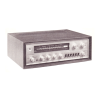
Instructions for removing the wooden cabinet cover.
Instructions for removing the bottom plate.
Instructions for removing the heat sink assembly.
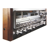
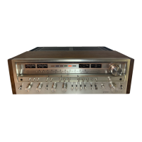
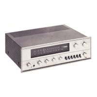
Diagram identifying components on the front panel.
Diagram identifying components with the front panel removed.
Diagram identifying components from the top view.
Diagram identifying components from the bottom view.
Diagram identifying connectors and components on the rear panel.
Procedures for adjusting power amplifier DC balance and idle current.
Steps for calibrating the output power meters.
Detailed steps for calibrating the FM tuner section.
Procedures for adjusting the multiplex decoder circuit.
Steps for adjusting the Automatic Pilot Control circuit.
Detailed steps for calibrating the AM tuner section.
Glossary of screw, washer, and nut symbols and descriptions.
Illustrates how to interpret part labels in exploded views.
Exploded view of the receiver's external parts.
Exploded view of the top plate and associated parts.
Exploded view of the front internal chassis components.
Exploded view of the rear internal chassis components.
Exploded view of the bottom internal chassis components.
Exploded view of the rear panel connections and parts.
External appearance and pinouts of various transistors and ICs.
Comprehensive list of miscellaneous components.
Schematic diagrams for integrated circuits.
Schematic diagram for the FM front end module.
Complete schematic diagrams for the entire receiver.
Schematic diagram of the tuner assembly.
Schematic diagram of the tuner assembly.
Schematic diagram of the tuner assembly.
List of coils used in the tuner assembly.
List of capacitors used in the tuner assembly.
List of resistors used in the tuner assembly.
List of semiconductors used in the tuner assembly.
Schematic diagram and parts list for the slide switch assembly.
Schematic diagram and parts list for the cartridge load assembly.
Schematic diagram of the APC assembly.
List of components for the APC assembly.
Schematic diagram of the equalizer amplifier assembly.
List of components for the EQ amplifier assembly.
Schematic diagram of the function selector assembly.
List of components for the function selector assembly.
Schematic diagram of the APC control and microphone assembly.
List of components for the APC control/mic assembly.
Schematic diagram of the tone control assembly.
List of components for the tone control assembly.
Schematic diagram of the filter assembly.
List of components for the filter assembly.
Schematic diagram of the rectifier L assembly.
List of components for the rectifier L assembly.
Schematic diagram of the power amplifier L assembly.
List of components for the power amplifier L assembly.
Schematic diagram of the power amplifier R assembly.
List of components for the power amplifier R assembly.
Schematic diagram of the meter amplifier assembly.
List of components for the meter amplifier assembly.
Schematic diagram of the rectifier R assembly.
List of components for the rectifier R assembly.
Schematic diagram of the power supply assembly.
List of components for the power supply assembly.
Compares miscellaneous parts across different receiver models.
Additional information specific to the HG model.
Exploded view of the rear panel for HG model type.
Schematic diagram specific to the HG model type.
Schematic and parts list for HG meter amplifier assembly.
Schematic and parts list for HG power supply assembly.
Additional information specific to S and S/G models.
Exploded view of the rear panel for S and S/G model types.
Schematic diagram specific to S and S/G model types.
Schematic and parts list for the 5P connector assembly.
List of components for the 5P connector assembly.
Differences in miscellaneous parts for KC type compared to KU type.
Information regarding changes to zener diodes in the power supply assembly.
Details on circuit modifications for the power supply assembly.
| Power Output | 270 watts per channel into 8Ω (stereo) |
|---|---|
| Total Harmonic Distortion | 0.03% |
| Frequency Response | 5Hz to 100kHz |
| Tuning Range | FM, MW |
| Input Sensitivity | 2.5mV (MM), 150mV (line) |
| Year Introduced | 1978 |
| Output | 150mV (line) |