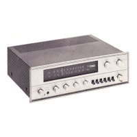
Do you have a question about the Pioneer SX-1000TD and is the answer not in the manual?
| line requirements | 110V, 117V, 130V, 220V, and 240V |
|---|---|
| power consumption | 200 watts |
| RMS rated power output | 50 watts per channel |
| harmonic distortion | Less than 0.5% at 1kHz rated output |
|---|---|
| hum & noise (TAPE HEAD) | better than 75dB |
| hum & noise (MAG) | better than 80dB |
| weight | 10.6 kg |
|---|---|
| width | 405 mm |
| height | 137 mm |
| depth | 335 mm |
Highlights FET front-end and IC for FM tuner performance.
Discusses MPX, muting, SEPP output, and power transistor protection.
Advice on placing the unit to ensure optimal performance and safety.
Guide on how to adjust line voltage and check the fuse.
Procedure for replacing a blown fuse with a new one.
Details for connecting main and extra speaker systems.
Connections for AM and FM antennas, and grounding.
Controls speaker system selection and headphone jack.
Tuning control, tuning meter, and FM stereo indicator.
Controls for selecting input sources and operational modes.
Controls for bass, treble, balance, volume, loudness, and filters.
Switches for FM muting and automatic frequency control.
Terminals for AM/FM antennas and grounding.
Jacks for connecting turntables, tape decks, and auxiliary devices.
Terminals for connecting main and extra speaker systems.
Separation control, DIN connector, and voltage/fuse selector.
Auxiliary power outlets and the main power cord.
Guidance on positioning and connecting AM antennas.
Instructions for indoor T-antenna and outdoor FM antenna.
Proper grounding for noise reduction.
Procedure for connecting a single speaker set.
Connects tape decks lacking a preamplifier.
Connects turntables using magnetic cartridges.
Connects turntables using ceramic or crystal cartridges.
Connecting for recording audio program material.
Connecting for tape playback and monitoring.
Using the integrated DIN connector for tape recorders.
Tuning and receiving FM mono and stereo broadcasts.
Tuning and receiving AM broadcasts.
Playing records via PHONO inputs.
Using the receiver with a tape recorder for recording and playback.
Monitoring tape recordings using the tape monitor function.
Diagnosing and correcting noise issues during broadcasts.
Diagnosing and correcting noise issues during record playback.
Troubleshooting power-on failures and howling during playback.
Step-by-step alignment for the AM tuner section.
Step-by-step alignment for the MPX (multiplex) section.
Detailed procedures for aligning the FM tuner section.
Visual guide for routing the dial cord.
Diagrams showing the arrangement of internal circuit units.
Lists of capacitors, diodes, and transistors used.
Lists of resistors, coils, and transformers used.
Lists of switches, compound parts, and potentiometers.
List of miscellaneous electronic parts.
Capacitors used in FM front-end and IF units.
Resistors used in FM front-end and IF units.
Lists of coils, transformers, diodes, and transistors.
Lists of diodes, transistors, coils, and transformers.
Lists of compound parts and potentiometers.
Capacitors, diodes, and transistors for the FM MPX unit.
Lists of resistors for different circuit units.
Lists of compound parts and potentiometers.
Components for AM Tuner and Pre Amp. units.
Transistors, capacitors, and resistors for the Control Amp. Unit.
Transistors and capacitors for the Main Amp. Unit.
Lists of diodes and transistors.
Potentiometers, resistors, capacitors, and diodes/transistors for the PSU.
Circuit diagram of the AM Tuner Unit.
Circuit diagram of the FM IF Unit.
Circuit diagram of the FM MPX Unit.
Circuit diagram of the Main Amplifier Unit.
Circuit diagram of the Pre-Amplifier Unit.
Circuit diagram of the Control Amplifier Unit.
Circuit diagram of the Power Supply Unit.
Visual representation of the receiver's main functional blocks.
Detailed circuit diagram for the AM Tuner Unit.
Detailed circuit diagram for the FM IF Unit.
Detailed circuit diagram for the FM MPX Unit.
Printed circuit board layout for the Pre-Amplifier Unit.
Printed circuit board layout for the Control Amplifier Unit.
Printed circuit board layout for the Main Amplifier Unit.
Printed circuit board layout for the Power Supply Unit.
Lists transistors and diodes used in tuner and audio sections.
Technical details for FM tuner performance and sensitivity.
Technical details for multiplex circuitry and channel separation.
Technical details for AM tuner performance.
Technical details for audio output power and performance.
Specifications for input sensitivities and output terminals.
Details on equalization, tone controls, and filters.
Specifications for loudness contour, power, and line requirements.
 Loading...