Do you have a question about the Pioneer SX-1010 and is the answer not in the manual?
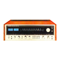
Controls for selecting speaker outputs A, B, and C.
Meters for AM/FM tuning and stereo reception indicator.
Buttons to select input sources like AM, FM, Phono, AUX.
Adjustments for bass, treble, and tone defeat.
Muting, Mode selection, and Loudness compensation.
Switches for tape dubbing and monitoring.
Power switch, headphone jacks, and volume control.
Switches for Dolby NR and 4-channel adaptors.
Describes the flow of audio signals through the unit.
Details the reception and tuning circuits for FM and AM.
Explains how input signals are selected and routed.
Describes the pre-amplifier, control amplifier, and power amplifier stages.
Covers speaker selection and protective circuitry.
Procedures for tuning and calibrating the FM receiver section.
Steps for aligning the FM stereo multiplex decoder.
Procedures for tuning and calibrating the AM receiver section.
Calibration steps for the output amplifier stages.
List of components and their part numbers for the first exploded view.
List of components and their part numbers for the second exploded view.
Overall wiring diagram and list of common electronic components.
Schematic and parts list for the FM front-end receiver stage.
Schematic and parts list for the tuner assembly.
Schematic and parts list for the muting circuit.
Schematic and parts list for the equalizer amplifier.
Schematic and parts list for the control amplifier.
Schematic and parts list for the power amplifier.
Schematic and parts list for the protection circuit.
Schematic and parts list for the power supply circuit.
Schematic and parts list for an alternative power supply circuit.
Schematic and parts list for the speaker selection switch circuit.
Schematic and parts list for the dimmer/FM mute switch circuit.
Schematic and parts list for the function selection switch circuit.
Schematic and parts list for the mode/loudness switch circuit.
Schematic and parts list for the filter/muting switch circuit.
Schematic and parts list for tape/adaptor switch circuits.
Schematic and parts list for the 5-pin connector assembly.
Wiring diagram and component list for the 220V model.
Schematic and parts list for the 220V power supply circuit.
| Power Output | 100 watts per channel into 8Ω (stereo) |
|---|---|
| Tuning Range | FM, MW |
| Input Sensitivity | 2.5mV (MM), 150mV (line) |
| Speaker Load Impedance | 4Ω to 16Ω |
| Total Harmonic Distortion | 0.1% |
| Signal to Noise Ratio | 95dB (line) |
| Output | 150mV (line) |
| Semiconductors | 67 x transistors |
| Channel Separation | 55dB (line) |