Do you have a question about the Pioneer SX-1250 and is the answer not in the manual?
Covers power output, distortion, sensitivity, frequency response, S/N ratio, etc.
Controls for AM, FM, PHONO, AUX, tape, Volume, Muting, Loudness.
Speaker selection, headphone jack, tone, filter, bass/treble controls.
Tuning knob, FM Muting, Multipath, Volume, Balance controls.
Diagrams for connecting antennas, turntables, tape players, and speakers.
Description of FM Front End and IF Section circuitry.
Explanation of PLL, stereo detector, and demodulator circuits.
Description of equalizer amp and tape monitor/duplicate circuits.
Description of active filters and the power amplifier section.
Circuits for relay drive, overload, and center point detection.
Regulated power supply and inrush current suppressor circuit.
Block diagrams for tuner and equalizer amplifier sections.
Instructions for removing the top and bottom plates.
Steps to remove the front panel and its knobs.
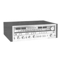
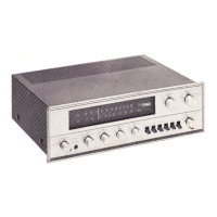
Identification of knobs and switches on the front panel.
Identification of rear panel input/output terminals and holders.
Step-by-step procedure for tuning the AM section.
Procedures for aligning the FM front end and tuner assembly.
Procedures for adjusting bias and voltage in the power amplifier.
Step-by-step guide for stringing the dial cord.
List and shapes of screws, washers, and nuts used.
Exploded view of the front panel, knobs, and associated parts.
| Total Harmonic Distortion | 0.1% |
|---|---|
| Tuning Range | FM, MW |
| Input Sensitivity | 2.5mV (MM), 150mV (line) |
| Speaker Load Impedance | 4Ω to 16Ω |
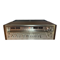
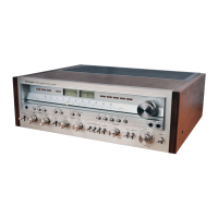
| Type | Stereo Receiver |
| Year Introduced | 1976 |
| Power Output | 160 W per channel into 8Ω (stereo) |
| Signal to Noise Ratio | 90dB (line) |
| Semiconductors | 45 x diodes |