Do you have a question about the Pioneer SX-1000TW and is the answer not in the manual?
Instructions for selecting the correct line voltage and fuse for safe operation.
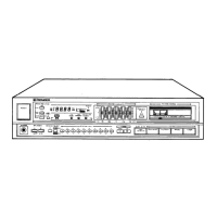
Controls speaker selection and power status for the unit.
Indicates when an FM station is broadcasting in stereo.
Meter indicates optimum tuning points for AM or FM stations.
Adjusts the receiver to the desired AM or FM station.
Selects program material source: AM, FM MONO, FM AUTO, or PHONO.
Stereo headphone jack for private listening.
Adjusts the bass response of the audio output.
Adjusts the treble response of the audio output.
Balances the volume level between the left and right channels.
Adjusts the overall listening volume level.
Enhances bass and treble at low listening volumes.
Eliminates low-frequency noise like record rumble or hum.
Eliminates high-frequency noise like record scratch or hiss.
Eliminates inter-station noise during FM tuning.
Activates automatic frequency control to stabilize FM tuning.
Selects between PHONO 1 and PHONO 2 input sources.
Selects stereo/mono mode and tape monitoring functions.
Built-in antenna for AM station reception.
Adjusts FM multiplex stereo channel separation.
Provides switched power to external equipment.
Provides continuous power to external equipment.
Connection point for an external AM antenna.
Connection point for a receiver ground lead.
Connection points for FM antenna.
Inputs for direct tape head output signals.
Inputs for magnetic pickup turntable 1.
Inputs for magnetic pickup turntable 2.
Connection point for turntable ground lead.
Inputs for ceramic or crystal pickup turntables.
Inputs for auxiliary audio signals, e.g., from a TV.
Inputs for tape recorder playback or monitor signals.
Outputs for recording signals to a tape recorder.
DIN connector for simplified tape recorder connection.
AC power cord for connecting to a wall socket.
Connects right channel main loudspeakers.
Connects left channel main loudspeakers.
Connects right channel extra loudspeakers.
Connects left channel extra loudspeakers.
Instructions for connecting AM antennas, including loopstick and lead types.
Guidance for connecting indoor T-shaped and outdoor FM antennas.
Details on connecting one or two loudspeaker systems to the receiver.
Inputs for direct tape head output signals from tape decks.
How to connect turntables with magnetic cartridges.
How to connect turntables with ceramic or crystal cartridges.
Procedure for connecting the receiver to a tape recorder for recording.
Connecting for tape playback and monitoring recorded tapes.
Using the DIN connector for simplified tape recorder operation.
Step-by-step guide to tuning and receiving FM radio broadcasts.
Instructions for tuning and receiving AM radio broadcasts.
How to play back records using the turntable inputs.
Playing back signals directly from tape deck heads.
Procedure for recording audio signals to a tape recorder.
Procedure for playing back recorded tapes through the receiver.
Monitoring recording progress with a 2- or 3-head tape recorder.
Diagnosing and remedying various noises encountered during broadcast reception.
Troubleshooting noise issues specifically related to record playback.
Diagnosing why the unit may not power on.
Addressing howling sounds caused by volume or turntable setup.
List of capacitors used in the unit with their specifications.
List of diodes and transistors with part numbers.
List of resistors with values and specifications.
List of switches used in the unit with part numbers.
List of compound parts and their specifications.
List of potentiometers with values and part numbers.
List of other miscellaneous components and units.
Capacitors specific to the FM Front-End Unit.
Resistors specific to the FM Front-End Unit.
Capacitors specific to the FM IF Unit.
Resistors specific to the FM IF Unit.
Coils and transformers for the FM IF Unit.
Diodes and transistors for the FM IF Unit.
Resistors for the FM IF Unit.
Capacitors specific to the AM Tuner Unit.
Resistors specific to the AM Tuner Unit.
Diodes and transistors for the AM Tuner Unit.
Coils and transformers for the AM Tuner Unit.
Potentiometers for the AM Tuner Unit.
Capacitors specific to the FM MPX Unit.
Resistors specific to the FM MPX Unit.
Diodes and transistors for the FM MPX Unit.
Capacitors specific to the Control Amp Unit.
Resistors specific to the Control Amp Unit.
Capacitors specific to the Main Amp Unit.
Resistors specific to the Main Amp Unit.
Resistors specific to the Main Amp Unit.
Potentiometers specific to the Main Amp Unit.
Capacitors specific to the Power Supply Unit.
Resistors specific to the Power Supply Unit.
Diodes and transistors for the Power Supply Unit.
Details on ICs, transistors, FETs, and diodes used in the unit.
Technical specifications for the FM tuner section.
Technical specifications for the Multiplex (MPX) section.
Technical specifications for the AM tuner section.
Technical specifications for the audio output stage.
Specifications for power requirements, dimensions, and weight.
| frequency response | 20Hz to 50kHz |
|---|---|
| frequency range FM | 87-108 MHz |
| frequency range AM | 525-1605 kHz |
| harmonic distortion | less than 0.5% at 1kHz rated output |
|---|---|
| hum and noise tape head | better than 75dB |
| hum and noise mag | better than 80dB |
| input impedance magnetic phono | 2.4mV, 50k ohms |
|---|---|
| input impedance ceramic phono | 51mV, 90k ohms |
| input impedance tape head | 1.5mV, 120k ohms |
| power requirements | 110V, 117V, 130V, 220V, 240V switchable |
|---|---|
| power consumption | 285VA, 255W max |
| power output per channel | 50 watts per channel |
| width | 405 mm |
|---|---|
| height | 137 mm |
| depth | 350 mm |
| weight without package | 10.6 kg |
| weight with package | 13.3 kg |