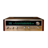
Do you have a question about the Pioneer SX-525 and is the answer not in the manual?
Block diagram illustrating the overall circuit architecture of the receiver.
Detailed description of the main amplifier unit's circuit.
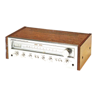
Procedure for removing the wooden case from the receiver housing.
Steps for removing the front panel assembly from the unit.
Instructions for removing the bottom plate of the receiver.
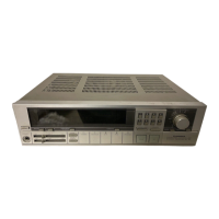
Identification of components and PCBs visible from the top view.
Identification of components and PCBs visible from the bottom view.
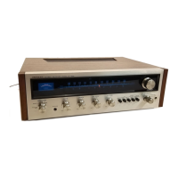
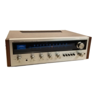
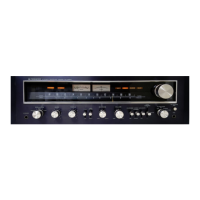
Identification of components and controls on the front panel.
Procedure for aligning the FM Intermediate Frequency (IF) section.
Procedure for aligning the AM Intermediate Frequency (IF) section.
Procedure for tuning the FM tracking alignment for optimal reception.
Procedure to check the FM muting function's operation.
Procedure for tuning the AM tracking alignment for optimal reception.
Procedure for aligning the FM Multiplex (MPX) decoder circuit.
Procedure to check the performance of the SCA filter.
Procedure to check the operation of the stereo indicator lamp.
Diagram showing unit connections and a list of miscellaneous parts.
Schematic and parts list for the Tuner Unit (AWE-003).
Detailed list of components for the Tuner Unit.
Schematic and parts list for the Head Amp Unit (AWF-003).
Detailed list of components for the Head Amp Unit.
Schematic and parts list for the Control Amp Unit (AWG-011).
Detailed list of components for the Control Amp Unit.
Schematic and parts list for the Main Amp Unit.
Detailed list of components for the Main Amp Unit.
Schematic and parts list for the Power Supply Unit.
Detailed list of components for the Power Supply Unit.
Schematic and parts list for the Switch Unit (AWS-015).
Detailed list of components for the Switch Unit.
Schematic and parts list for the CR Unit (AWX-012/AWX-013).
Detailed list of components for the CR Unit.
| Total Harmonic Distortion | 0.8% |
|---|---|
| Input Sensitivity | 2.5mV (MM), 150mV (line) |
| Tuning Range | FM, MW |
| Damping Factor | 30 |
| Speaker Load Impedance | 4Ω to 16Ω |
| Power Output | 27 watts per channel into 8Ω (stereo) |
| Frequency Response | 20Hz to 20kHz |
| Signal to Noise Ratio | 70dB (MM) |
| Semiconductors | 3 x IC, 2 x FET, 16 x transistors, 14 x diodes |
| Channel Separation | 45dB (MM), 50dB (line) |