Do you have a question about the Pioneer vsx-421-k and is the answer not in the manual?
Diagram illustrating the assembly of exterior parts for specific receiver models.
Details part numbers for the Audio Assembly across different receiver models.
Details part numbers for the Front Assembly across different receiver models.
Details part numbers for the AMP7 Assembly across different receiver models.
Details part numbers for the AMP5 Assembly across different receiver models.
Details part numbers for the Main Assembly across different receiver models.
Details part numbers for the Subwoofer Assembly across different receiver models.
Details part numbers for the Video Assembly across different receiver models.
Diagrams showing exterior part assemblies for VSX-521 and VSX-421 models.
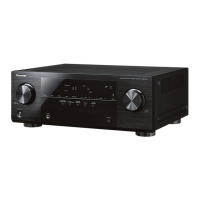
This document is a service manual for Pioneer Audio/Video Multi-Channel Receivers, specifically models VSX-826-K, VSX-821-K, VSX-521-K, and VSX-421-K. It provides essential information for servicing and maintaining these devices, focusing on the interchangeability and differences in parts across various models and types.
The primary function of these devices is to act as audio/video multi-channel receivers, centralizing the management and output of audio and video signals to multiple channels. They are designed to deliver a comprehensive home entertainment experience, integrating various audio and video sources.
For usage, the manual directs users to refer to the operating instructions for details on specifications and panel facilities. This suggests that the receivers offer a range of input and output options, along with user-friendly controls for managing audio and video settings. The presence of a remote control (AXD7621, AXD7622, AXD7619, AXD7618, AXD7620) indicates convenience in operation from a distance. The inclusion of a microphone for Auto MCACC setup implies an automatic calibration feature, optimizing audio performance based on the room environment. Operating instructions are provided in multiple languages (English, French, Spanish, German, Italian, Dutch, Russian), ensuring accessibility for a diverse user base. A CD-ROM with operating instructions is also mentioned, offering a digital alternative.
Maintenance features are a core focus of this service manual. It emphasizes the importance of using identical parts for replacement, especially for components marked with a specific symbol, which indicates a critical safety factor. This highlights a commitment to safety and proper functioning during servicing. The manual provides detailed contrast tables for various PCB assemblies (MAIN, SUBWOOFER, AMP5, AMP7, VIDEO, CPU, STANDBY, FRONT, AUDIO, USB, BRIDGE B, MIC) and exterior sections, outlining which parts are interchangeable or differ across models and types. This information is crucial for technicians to identify and order the correct replacement parts.
The document also offers guidance on ordering resistors, instructing technicians to convert resistance values into code form using specific examples. This ensures accuracy in part identification and ordering. For lubricants or glue, the manual advises following specific instructions or applying an appropriate amount if no instructions are given. This attention to detail in material application is important for the longevity and performance of the device.
The "EXPLODED VIEWS" section, referenced for exterior parts, provides visual aids for disassembly and reassembly, which is invaluable for technicians. The notes throughout the manual, such as those regarding "NSP" (Not in our Master Spare Parts List) parts, help manage expectations about part availability. The manual also clarifies that some PCB assemblies, while having different part numbers, may consist of the same service components, simplifying inventory and replacement decisions.
Overall, this service manual is a comprehensive guide for technicians, ensuring that the Pioneer Audio/Video Multi-Channel Receivers can be effectively serviced, maintained, and repaired, thereby extending their operational life and ensuring continued high-quality audio and video performance.
| Amplifier Type | Discrete |
|---|---|
| Channels | 5.1 |
| HDMI Inputs | 4 |
| HDMI Outputs | 1 |
| Network Capability | No |
| 3D Support | Yes |
| Audio Return Channel (ARC) | Yes |
| Component Video Inputs | 2 |
| Composite Video Inputs | 3 |
| Digital Audio Inputs (Optical) | 2 |
| Digital Audio Inputs (Coaxial) | 1 |
| Headphone Output | Yes |
| Bluetooth | No |
| Wi-Fi | No |
| Ethernet | No |
| AM/FM Tuner | Yes |
| Audio Formats Supported | Dolby TrueHD, DTS-HD Master Audio |
| Video Upconversion | Yes |
| USB Port | Yes |
| Power Output | 110W per channel (6 ohms, 1 kHz, THD 1%, 1ch driven) |
| Dimensions (W x H x D) | 435 x 151 x 329 mm |