Do you have a question about the Pioneer XR-P270C and is the answer not in the manual?
| CD Player | Yes |
|---|---|
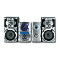
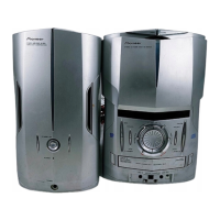
| Type | Stereo System |
| Speaker Configuration | 2-Way |
| Tuner Type | AM/FM |
| Power Source | AC Power |
Details the laser interlock mechanism and potential exposure risks.
Illustrates packing components and lists related parts.
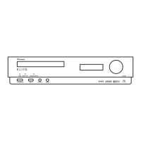
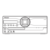
Shows an exploded view of the exterior components (part 1 of 3).
Details the disassembly and parts of the CD loading mechanism.
Lists parts and shows an exploded view of the servo mechanism.
Shows the overall system connections and the TRANS ASSY schematic.
Schematic diagram for the AF (Audio Frequency) assembly.
Schematic diagram for the power supply assembly.
Schematics for display, LCD, and lamp assemblies.
PCB connection diagram for the TRANS ASSY.
PCB connection diagrams for motor, SW, and CD assemblies.
PCB connection diagrams for power, CD SW, and LED assemblies.
Comprehensive list of all PCB assemblies and their part numbers.
Compares PCB assemblies across different models, highlighting differences.
Lists semiconductor, coil, capacitor, and resistor parts for the Power Assy.
Lists semiconductor and component parts for the LCD Assy.
Adjustment procedures for FM and AM tuner sections.
Adjustment procedures for the cassette deck section, including tape speed.
Adjustment procedure for the Vp voltage in the power supply section.
Guide on how to enter and exit test modes for CD functions.
Lists key IC parts and their functions, with pin assignments.
Specific IC details: block diagram, pin functions, and related components.
Specific IC details: block diagram, pin functions, and related components.
Detailed troubleshooting steps for common system failures and error codes.
Overall block diagram of the power supply system.